2ZR-FE FUEL FUEL INJECTOR INSTALLATION
PROCEDURE

 23250
1.INSTALL FUEL INJECTOR ASSEMBLY
23250
1.INSTALL FUEL INJECTOR ASSEMBLY
- HINT:
-
Perform "Inspection After Repair" after replacing a fuel injector assembly.
-
Click hereEngine / Hybrid System>2ZR-FE ENGINE CONTROL>SFI SYSTEM>INITIALIZATION
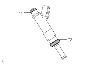
| *1 | O-ring |
| *2 | Injector Vibration Insulator |
Apply a light coat of gasoline or spindle oil to new injector vibration insulators and new O-rings, and then install one to each fuel injector assembly.
Apply a light coat of gasoline or spindle oil where the fuel delivery pipe sub-assembly contacts each O-ring.
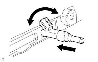
While turning the fuel injector assembly left and right, install it to the fuel delivery pipe sub-assembly.
- NOTICE:
- ·
Do not damage the fuel injector assembly or O-ring.
·Make sure that the O-ring is not twisted or moved out of place when installing the fuel injector assembly.
·After installing each fuel injector assembly, check that it turns smoothly. If not, replace the O-ring with a new one.
- HINT:
-
Use the same procedure to install the other fuel injector assemblies.
23807V
2.INSTALL NO. 1 DELIVERY PIPE SPACER
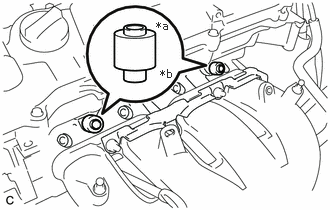
| *a | Fuel Delivery Pipe Sub-assembly Side |
| *b | Cylinder Head Sub-assembly Side |
Install the 2 No. 1 delivery pipe spacers to the cylinder head sub-assembly.
- NOTICE:
-
Install the No. 1 delivery pipe spacers in the correct direction.
23807
3.INSTALL FUEL DELIVERY PIPE SUB-ASSEMBLY
Install the fuel delivery pipe sub-assembly with the 4 fuel injector assemblies with the 2 bolts.
- Torque:
- 21 N*m (214 kgf*cm, 15 ft.*lbf)
- NOTICE:
- ·
Be careful not to drop the fuel injector assemblies when installing the fuel delivery pipe sub-assembly.
·Check that the fuel injector assemblies turn smoothly after installing the fuel delivery pipe sub-assembly.
Install the clamp of the fuel delivery pipe sub-assembly to the cylinder head sub-assembly with the bolt.
- Torque:
- 21 N*m (214 kgf*cm, 15 ft.*lbf)
89426
4.INSTALL VACUUM SENSOR BRACKET
Install the vacuum sensor bracket to the intake manifold with the engine cover joint.
- Torque:
- 8.0 N*m (82 kgf*cm, 71 in.*lbf)
89421
5.INSTALL VACUUM SENSOR (E.F.I. VACUUM SENSOR ASSEMBLY)
23901
6.CONNECT FUEL TUBE SUB-ASSEMBLY
- NOTICE:
-
Check that there is no damage or foreign matter on the connecting parts of the fuel lines.
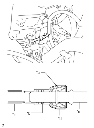
| *a | Retainer |
| *b | O-ring |
| *c | Nylon Tube |
| *d | Fuel Tube Connector |
| *e | Fuel Pipe |
Connect the fuel tube sub-assembly to the fuel delivery pipe sub-assembly.
Align the fuel tube connector with the fuel pipe, and push them together until the fuel tube connector makes a "click" sound. If it is difficult to push the fuel pipe into the fuel tube connector, apply a small amount of clean engine oil to the tip of the fuel pipe and reinsert it.
After connecting the fuel lines, check that the fuel pipe and fuel tube connector are securely connected by pulling on them.
Engage the 2 claws to install a new No. 2 fuel pipe clamp.
25719
7.INSTALL VACUUM SURGE TANK
82121
8.CONNECT ENGINE WIRE
Connect the engine wire and install the 3 bolts and 3 nuts as shown in the illustration.
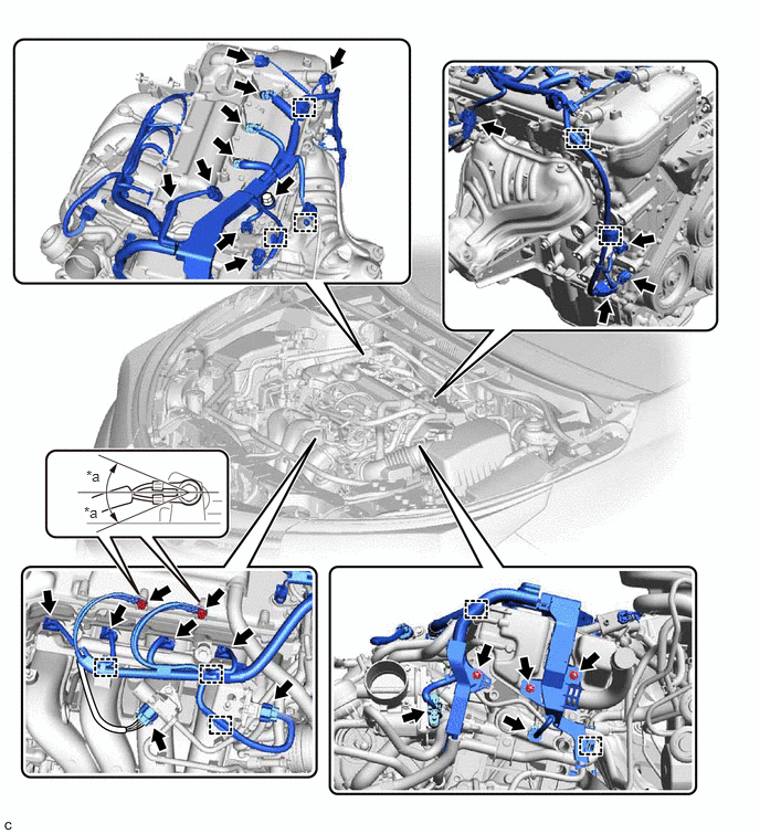
| *a | 20° | - | - |
- Torque:
- 8.4 N*m (86 kgf*cm, 74 in.*lbf)
- HINT:
-
It is acceptable for the ground wires to be tilted +20° to -20°.
Engage the 10 clamps, and then connect the 21 connectors.
17701
9.INSTALL AIR CLEANER CASE SUB-ASSEMBLY
17705
10.INSTALL AIR CLEANER CAP WITH AIR CLEANER HOSE
11.CONNECT CABLE TO NEGATIVE BATTERY TERMINAL
- NOTICE:
-
When disconnecting the cable, some systems need to be initialized after the cable is reconnected.
-
Click hereGeneral>INTRODUCTION>REPAIR INSTRUCTION>INITIALIZATION
12.INSPECT FOR FUEL LEAK
11212
13.INSTALL NO. 2 CYLINDER HEAD COVER
14.PERFORM INITIALIZATION
Perform "Inspection After Repair" after replacing a fuel injector assembly.
Click hereEngine / Hybrid System>2ZR-FE ENGINE CONTROL>SFI SYSTEM>INITIALIZATION