SUPPLEMENTAL RESTRAINT SYSTEMS SPIRAL CABLE REMOVAL
PROCEDURE

 45100
1.REMOVE STEERING WHEEL ASSEMBLY
45100
1.REMOVE STEERING WHEEL ASSEMBLY
2. ALIGN FRONT WHEELS FACING STRAIGHT AHEAD
84306
3.INSPECT SPIRAL CABLE SUB-ASSEMBLY (w/o VSC)
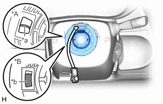
| *A | Flat Cable Type |
| *B | Colored Roller Type |
| *a | Flat Cable |
| *b | Colored Roller |
Check the colored roller or flat cable shown in the illustration.
If the colored roller or flat cable shown in the illustration cannot be confirmed, it is possible that the spiral cable sub-assembly is broken. Replace the spiral cable sub-assembly with a new one.
84307
4.INSPECT SPIRAL CABLE WITH SENSOR SUB-ASSEMBLY (w/ VSC)
| *A | Flat Cable Type |
| *B | Colored Roller Type |
| *a | Flat Cable |
| *b | Colored Roller |
Check the colored roller or flat cable shown in the illustration.
If the colored roller or flat cable shown in the illustration cannot be confirmed, it is possible that the spiral cable sub-assembly is broken. Replace the spiral cable with sensor sub-assembly with a new one.
45287
5.REMOVE LOWER STEERING COLUMN COVER
45286B
6.REMOVE UPPER STEERING COLUMN COVER
84306
7.REMOVE SPIRAL CABLE SUB-ASSEMBLY (w/o VSC)
Check that the ignition switch is off.
Check that the cable is disconnected from the negative (-) battery terminal.
- CAUTION:
-
Wait at least 90 seconds after disconnecting the cable from the negative (-) battery terminal to disable the SRS system.
Check that the front wheels are facing straight ahead.
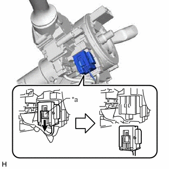
| *a | Slider |
Slide the slider to release the lock, and then disconnect the yellow airbag connector from the spiral cable sub-assembly.
- NOTICE:
-
When disconnecting any airbag connector, take care not to damage the airbag wire harness.
Disconnect the other connectors from the spiral cable sub-assembly.
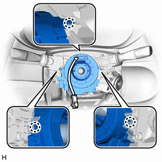
Disengage the 3 claws to remove the spiral cable sub-assembly.
84307
8.REMOVE SPIRAL CABLE WITH SENSOR SUB-ASSEMBLY (w/ VSC)
- NOTICE:
- ·
Do not replace the spiral cable with sensor sub-assembly with the battery connected and the ignition switch ON.
·Do not rotate the spiral cable with sensor sub-assembly without the steering wheel assembly installed, with the battery connected and the ignition switch ON.
·Ensure that the steering wheel assembly is installed and aligned straight when inspecting the steering sensor.
Check that the ignition switch is off.
Check that the cable is disconnected from the negative (-) battery terminal.
- CAUTION:
-
Wait at least 90 seconds after disconnecting the cable from the negative (-) battery terminal to disable the SRS system.
Check that the front wheels are facing straight ahead.
| *a | Slider |
Slide the slider to release the lock, and then disconnect the yellow airbag connector from the spiral cable with sensor sub-assembly.
- NOTICE:
-
When disconnecting any airbag connector, take care not to damage the airbag wire harness.
Disconnect the other connectors from the spiral cable with sensor sub-assembly.
Disengage the 3 claws to remove the spiral cable with sensor sub-assembly.
84306
9.REMOVE SPIRAL CABLE SUB-ASSEMBLY (w/ VSC)
- NOTICE:
- ·
Remove the steering sensor from the spiral cable sub-assembly only when replacing the spiral cable sub-assembly or the steering sensor.
·Removing the steering sensor from the spiral cable sub-assembly without using a lock pin may result in the center position of the steering sensor becoming misaligned. Therefore, make sure to use the lock pin provided with a new spiral cable sub-assembly when removing the steering sensor from the spiral cable sub-assembly.
·When replacing the steering sensor: Click hereBrake>BRAKE CONTROL / DYNAMIC CONTROL SYSTEMS>STEERING ANGLE SENSOR>REMOVAL
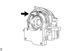
Install the lock pin to the steering sensor.
- NOTICE:
- ·
Use the lock pin provided with a new spiral cable sub-assembly.
·Do not remove the lock pin before installing the steering sensor to the spiral cable sub-assembly.
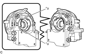
| *a | Guide |
Disengage the 6 claws and 2 pins, and remove the spiral cable sub-assembly from the steering sensor.
- NOTICE:
-
Do not damage the pins of the spiral cable sub-assembly or guides of the steering sensor.