LIGHTING (EXT) AUTOMATIC HEADLIGHT BEAM LEVEL CONTROL SYSTEM Headlight Leveling ECU Power Source Circuit
DESCRIPTION
This circuit detects the state of the ignition switch and sends it to the headlight leveling ECU assembly.
WIRING DIAGRAM
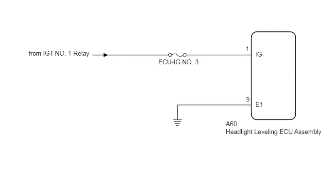
CAUTION / NOTICE / HINT
- NOTICE:
- ·
Inspect the fuses for circuits related to this system before performing the following procedure.
·If the headlight leveling ECU assembly has been replaced, it is necessary to initialize the headlight leveling ECU assembly.
Click hereVehicle Exterior>LIGHTING (EXT)>AUTOMATIC HEADLIGHT BEAM LEVEL CONTROL SYSTEM>INITIALIZATION
PROCEDURE
Connect the GTS to the DLC3.
Turn the ignition switch to ON.
Turn the GTS on.
Enter the following menus: Body Electrical / HL AutoLeveling / Data List.
Read the Data List according to the display on the GTS.
- Body Electrical > HL AutoLeveling > Data List
-
Tester Display Measurement Item Range Normal Condition Diagnostic Note +B IG power supply voltage value 0.00 to 19.75 V 11.00 to 14.00 V -
- Body Electrical > HL AutoLeveling > Data List
-
Tester Display +B - 50003 165 7
- OK:
Normal condition listed above is displayed.
- Result:
Proceed to OK NG
OK
Click hereVehicle Exterior>LIGHTING (EXT)>AUTOMATIC HEADLIGHT BEAM LEVEL CONTROL SYSTEM>PROBLEM SYMPTOMS TABLE
NG
Disconnect the A60 headlight leveling ECU assembly connector.
Measure the voltage according to the value(s) in the table below.
- Standard Voltage:
Tester Connection Condition Specified Condition A60-1 (IG) - Body ground Ignition switch off Below 1 V A60-1 (IG) - Body ground Ignition switch ON 11 to 14 V
- Result:
Proceed to OK NG
OK
NG
Measure the resistance according to the value(s) in the table below.
- Standard Resistance:
Tester Connection Condition Specified Condition A60-9 (E1) - Body ground Always Below 1 Ω
- Result:
Proceed to OK NG
OK
NG