BRAKE CONTROL / DYNAMIC CONTROL SYSTEMS VEHICLE STABILITY CONTROL SYSTEM U0073 Control Module Communication Bus OFF U0100 Lost Communication with ECM / PCM U0124 Lost Communication with Lateral Acceleration Sensor Module U0126 Lost Communication with Steering Angle Sensor Module
DESCRIPTION
The skid control ECU (brake actuator assembly) receives signals from the ECM, steering angle sensor and yaw rate and acceleration sensor (airbag ECU assembly) via CAN communication.
| DTC No. | Detection Item | DTC Detection Condition | Trouble Area |
|---|---|---|---|
| U0073 | Control Module Communication Bus OFF | Any of the following is detected:
1.
A bus OFF state occurs once or more within 0.1 seconds, 10 times in succession. (Sent signals cannot be received.) 2.
When the IG1 terminal voltage is between 10 and 17.4 V, a delay in receiving data from the yaw rate and acceleration sensor and steering angle sensor continues for 1 second or more. 3.
When the IG1 terminal voltage is between 10 and 17.4 V, the following occurs 10 times in succession within 60 seconds: ·
A delay in receiving data from the yaw rate and acceleration sensor and steering angle sensor occurs more than once within 5 seconds. |
CAN communication system |
| U0100 | Lost Communication with ECM / PCM | The IG1 terminal voltage is between 10 and 17.4 V and the vehicle speed is 15 km/h (9 mph) or more, data cannot be received from the ECM for 2 seconds or more. | ·
CAN communication system ·
Skid control ECU (brake actuator assembly) ·
ECM |
| U0124 | Lost Communication with Lateral Acceleration Sensor Module | Either of the following is detected:
1.
The IG1 terminal voltage is between 10 and 17.4 V and the vehicle speed is 7 km/h (4 mph) or more, data from the acceleration sensor cannot be received for 1 second or more. 2.
When the IG1 terminal voltage is between 10 and 17.4 V, the following occurs 10 times in succession within 60 seconds: ·
A data from the acceleration sensor cannot be received once or more within 5 seconds. |
·
CAN communication system ·
Skid control ECU (brake actuator assembly) ·
Acceleration sensor (airbag ECU assembly) |
| U0126 | Lost Communication with Steering Angle Sensor Module | Either of the following is detected:
1.
When the IG1 terminal voltage is between 10 and 17.4 V, data from the steering angle sensor cannot be received for 1 second or more. 2.
When the IG1 terminal voltage is between 10 and 17.4 V, the following occurs 10 times in succession within 60 seconds: ·
A data from the steering angle sensor cannot be received once or more within 5 seconds. |
·
CAN communication system ·
Skid control ECU (brake actuator assembly) ·
Steering angle sensor |
WIRING DIAGRAM
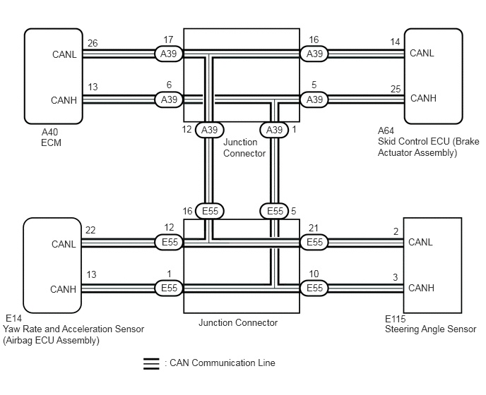
PROCEDURE
Using the GTS, check for any momentary interruption in the wire harness and connector corresponding to a DTC.
- Chassis > ABS/VSC/TRC > Data List
-
Tester Display Measurement Item Range Normal Condition Diagnostic Note EFI Communication Open ECM communication open detection Error or Normal Error: Momentary interruption
Normal: Normal- Yaw Rate Open Yaw rate sensor open detection Error or Normal Error: Momentary interruption
Normal: Normal- Deceleration Open Acceleration sensor open detection Error or Normal Error: Momentary interruption
Normal: Normal- Steering Open Steering angle sensor open detection Error or Normal Error: Momentary interruption
Normal: Normal-
- Chassis > ABS/VSC/TRC > Data List
-
Tester Display EFI Communication Open Yaw Rate Open Deceleration Open Steering Open - 50003 105 204,205,206,207
- Result:
Result Proceed to There is a constant interruption. (Error is displayed without interruption.) A There are no momentary interruptions. B There are momentary interruptions. (Error is displayed intermittently.) C
- HINT:
-
Perform the above inspection before disconnecting any sensors or connectors.
A
B
C
Turn the engine switch off.
Check if each sensor or ECM connector is securely connected.
- OK:
Each connector is securely connected.
- Result:
Proceed to OK NG
OK
NG
Turn the engine switch off.
Record the output DTCs (for VSC system and/or CAN communication system).
for VSC system: Click hereBrake>BRAKE CONTROL / DYNAMIC CONTROL SYSTEMS>VEHICLE STABILITY CONTROL SYSTEM>DTC CHECK / CLEAR
for CAN communication system: Click herePower Source / Network>NETWORKING>CAN COMMUNICATION SYSTEM>DIAGNOSIS SYSTEM
- Chassis > ABS/VSC/TRC > Trouble Codes
- 50001 105
- HINT:
-
If CAN communication system DTCs and related sensor DTCs are output simultaneously, troubleshoot the DTCs (for VSC system) after the CAN communication system returns to normal.
- Result:
Result Proceed to DTCs are not output. A DTCs are output. B CAN communication system DTC is output. C
A
Click hereGeneral>INTRODUCTION>HOW TO TROUBLESHOOT ECU CONTROLLED SYSTEMS>HOW TO PROCEED WITH TROUBLESHOOTING
B
C
Click herePower Source / Network>NETWORKING>CAN COMMUNICATION SYSTEM>HOW TO PROCEED WITH TROUBLESHOOTING
Turn the engine switch off.
Repair or replace the harness or connector.
Check for any momentary interruptions between the skid control ECU (brake actuator assembly) and each sensor or ECM.
- Result:
Proceed to NEXT
NEXT
Turn the engine switch off.
Clear the DTCs.
Click hereBrake>BRAKE CONTROL / DYNAMIC CONTROL SYSTEMS>VEHICLE STABILITY CONTROL SYSTEM>DTC CHECK / CLEAR
- Chassis > ABS/VSC/TRC > Clear DTCs
- 50002 105
Turn the engine switch off.
Start the engine.
Drive the vehicle at a speed of 15 km/h (9 mph) or more and turn the steering wheel to the right and left.
Check that no CAN communication system DTCs are output.
Click herePower Source / Network>NETWORKING>CAN COMMUNICATION SYSTEM>DIAGNOSIS SYSTEM
If VSC system DTCs are output, record them.
Click hereBrake>BRAKE CONTROL / DYNAMIC CONTROL SYSTEMS>VEHICLE STABILITY CONTROL SYSTEM>DTC CHECK / CLEAR
- Chassis > ABS/VSC/TRC > Trouble Codes
- 50001 105
- Result:
Result Proceed to DTCs are not output. A DTCs are output. B CAN communication system DTCs are output. C
- HINT:
-
The CAN communication system must be normal when performing troubleshooting for sensor DTCs (for VSC system).
A
B
C
Click herePower Source / Network>NETWORKING>CAN COMMUNICATION SYSTEM>HOW TO PROCEED WITH TROUBLESHOOTING