POWER ASSIST SYSTEMS POWER STEERING SYSTEM EPS Warning Light Circuit
DESCRIPTION
If the power steering ECU assembly detects a malfunction, the EPS warning light comes on. At this time, the power steering ECU assembly stores a DTC in its memory.
WIRING DIAGRAM
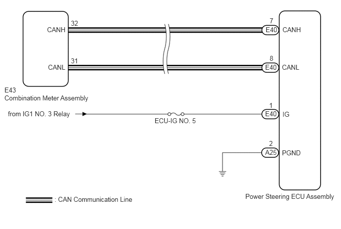
CAUTION / NOTICE / HINT
- NOTICE:
- ·
If the power steering ECU assembly has been replaced, perform assist map writing and torque sensor zero point calibration.
Click hereSteering>POWER ASSIST SYSTEMS>POWER STEERING SYSTEM>CALIBRATION
·Inspect the fuses for circuits related to this system before performing the following procedure.
PROCEDURE
Jiggle the power steering ECU assembly connectors and wire harness up and down, and left and right to check the illumination condition of the EPS warning light in the combination meter assembly.
- OK:
The EPS warning light illumination condition does not change.
- HINT:
-
When the EPS warning light is operating properly, it comes on when the ignition switch is turned to ON and goes off when the engine is started.
- Result:
Proceed to OK NG
OK
NG
Check for DTCs.
Click herePower Source / Network>NETWORKING>CAN COMMUNICATION SYSTEM>DIAGNOSIS SYSTEM
- Result:
Result Proceed to CAN communication system DTCs are not output. A CAN communication system DTCs are output. B
A
B
Click herePower Source / Network>NETWORKING>CAN COMMUNICATION SYSTEM>HOW TO PROCEED WITH TROUBLESHOOTING
Turn the ignition switch off.
Connect the GTS to the DLC3.
Turn the ignition switch to ON.
Turn the GTS on.
Enter the following menus: Chassis / EMPS / Data List.
Select the item "IG Power Supply" in the Data List and read the value displayed on the GTS.
- Chassis > EMPS > Data List
-
Tester Display Measurement Item Range Normal Condition Diagnostic Note IG Power Supply IG power source voltage Min.: 0.0000 V
Max.: 20.1531 V8 to 16 V Ignition switch ON
- Chassis > EMPS > Data List
-
Tester Display IG Power Supply - 50003 142 11
- OK:
The normal condition value is displayed on the GTS.
- Result:
Proceed to OK NG
OK
NG
Perform the Active Test of the combination meter assembly using the GTS.
- Body Electrical > Combination Meter > Active Test
-
Tester Display Indicat. EPS - 50004 122 22
Check the combination meter assembly.
- OK:
The EPS warning light turns on or off in accordance with the GTS operation.
- Result:
Proceed to OK NG
OK
NG
Click hereVehicle Interior>METER / GAUGE / DISPLAY>METER / GAUGE SYSTEM>HOW TO PROCEED WITH TROUBLESHOOTING
Disconnect the E40 and A25 power steering ECU assembly connectors.
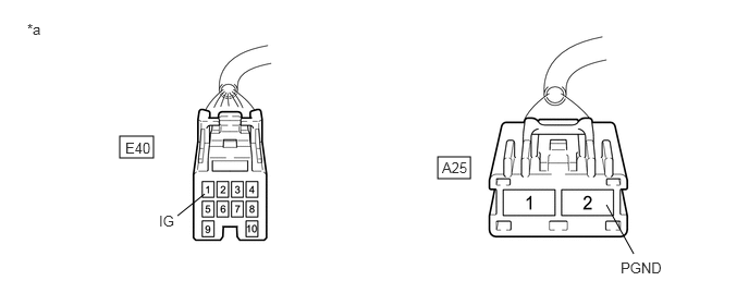
| *a | Front view of wire harness connector
(to Power Steering ECU Assembly) |
- | - |
Measure the voltage according to the value(s) in the table below.
- Standard Voltage:
Tester Connection Condition Specified Condition E40-1 (IG) - Body ground Ignition switch ON 8 to 16 V
Measure the resistance according to the value(s) in the table below.
- Standard Resistance:
Tester Connection Condition Specified Condition A25-2 (PGND) - Body ground Always Below 1 Ω
- Result:
Proceed to OK NG
OK
NG
Perform the Active Test of the combination meter assembly using the GTS.
- Body Electrical > Combination Meter > Active Test
-
Tester Display Indicat. EPS - 50004 122 22
Check the combination meter assembly.
- OK:
The EPS warning light turns on or off in accordance with the GTS operation.
- Result:
Proceed to OK NG
OK
NG
Click hereVehicle Interior>METER / GAUGE / DISPLAY>METER / GAUGE SYSTEM>HOW TO PROCEED WITH TROUBLESHOOTING