POWER ASSIST SYSTEMS POWER STEERING SYSTEM C1511 Torque Sensor1 C1512 Torque Sensor2 C1513 Torque Sensor Deviation Excessive C1514 Torque Sensor Power Supply Voltage C1517 Torque Hold
DESCRIPTION
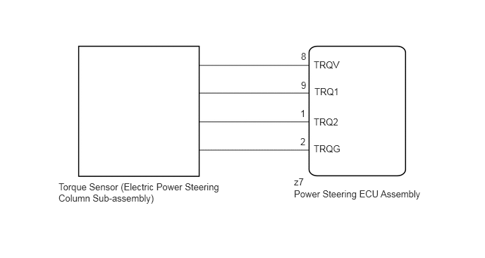
The torque sensor converts the rotation torque received from the steering wheel into electric signals and sends them to the power steering ECU assembly.
| DTC No. | Detection Item | DTC Detection Condition | Trouble Area | Warning Indicate | Return-to-normal Condition | Note |
|---|---|---|---|---|---|---|
| C1511 | Torque Sensor1 | Torque sensor malfunction | ·
Torque sensor (Electric power steering column sub-assembly) ·
Power steering ECU assembly |
EPS warning light: Comes on | Ignition switch ON again | - |
| C1512 | Torque Sensor2 | Torque sensor malfunction | ·
Torque sensor (Electric power steering column sub-assembly) ·
Power steering ECU assembly |
EPS warning light: Comes on | Ignition switch ON again | - |
| C1513 | Torque Sensor Deviation Excessive | Torque sensor malfunction | ·
Torque sensor (Electric power steering column sub-assembly) ·
Power steering ECU assembly |
EPS warning light: Comes on | Ignition switch ON again | - |
| C1514 | Torque Sensor Power Supply Voltage | Torque sensor malfunction | ·
Torque sensor (Electric power steering column sub-assembly) ·
Power steering ECU assembly |
EPS warning light: Comes on | Ignition switch ON again | - |
| C1517 | Torque Hold | Torque sensor malfunction | ·
Torque sensor (Electric power steering column sub-assembly) ·
Power steering ECU assembly |
EPS warning light: Comes on | Ignition switch ON again | - |
WIRING DIAGRAM
CAUTION / NOTICE / HINT
- NOTICE:
- ·
If the electric power steering column sub-assembly has been replaced, perform torque sensor zero point calibration.
Click hereSteering>POWER ASSIST SYSTEMS>POWER STEERING SYSTEM>CALIBRATION
·If the power steering ECU assembly has been replaced, perform assist map writing and torque sensor zero point calibration.
Click hereSteering>POWER ASSIST SYSTEMS>POWER STEERING SYSTEM>CALIBRATION
PROCEDURE
Check the connection condition of the torque sensor connector.
- OK:
Torque sensor connector is securely connected to the power steering ECU assembly.
- Result:
Proceed to OK NG
OK
NG
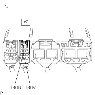
| *a | Component with harness connected
(Power Steering ECU Assembly) |
Turn the ignition switch to ON.
Measure the voltage according to the value(s) in the table below.
- Standard Voltage:
Tester Connection Condition Specified Condition z7-8 (TRQV) - z7-2 (TRQG) Ignition switch ON 4.5 to 5.5 V
- Result:
Proceed to OK NG
OK
NG
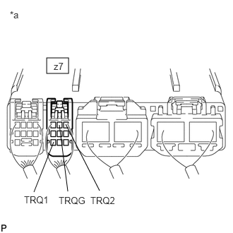
| *a | Component with harness connected
(Power Steering ECU Assembly) |
Start the engine.
Measure the voltage according to the value(s) in the table below.
- Standard Voltage:
Tester Connection Condition Specified Condition z7-9 (TRQ1) - z7-2 (TRQG) Engine running and steering wheel not being turned (without load) 2.3 to 2.7 V z7-1 (TRQ2) - z7-2 (TRQG) Engine running and steering wheel not being turned (without load) 2.3 to 2.7 V z7-9 (TRQ1) - z7-2 (TRQG) Engine running and steering wheel being turned to the right with vehicle stopped 2.5 to 3.8 V z7-1 (TRQ2) - z7-2 (TRQG) Engine running and steering wheel being turned to the right with vehicle stopped 1.2 to 2.5 V z7-9 (TRQ1) - z7-2 (TRQG) Engine running and steering wheel being turned to the left with vehicle stopped 1.2 to 2.5 V z7-1 (TRQ2) - z7-2 (TRQG) Engine running and steering wheel being turned to the left with vehicle stopped 2.5 to 3.8 V
Under each condition, measure the voltage at terminals TRQ1 and TRQ2, and calculate the sum.
- Standard Voltage:
Tester Connection Condition Specified Condition Sum of voltage between z7-9 (TRQ1) and z7-2 (TRQG) and voltage between z7-1 (TRQ2) and z7-2 (TRQG) Engine running and steering wheel not being turned (without load) Between 4.75 V and 5.25 V Engine running and steering wheel being turned to the right with vehicle stopped Engine running and steering wheel being turned to the left with vehicle stopped
- Result:
Proceed to OK NG
OK
NG