K313 CVT SHIFT LEVER INSTALLATION
PROCEDURE

 33554C
1.INSTALL SHIFT LOCK RELEASE BUTTON COVER
33554C
1.INSTALL SHIFT LOCK RELEASE BUTTON COVER
Engage the 2 claws to install the shift lock release button cover to the transmission floor shift assembly.
2.INSTALL TRANSMISSION FLOOR SHIFT ASSEMBLY
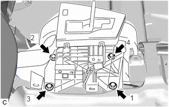
Temporarily install the transmission floor shift assembly to the vehicle body with the 4 bolts.
Fully tighten the 4 bolts in the order shown in the illustration to install the transmission floor shift assembly.
- Torque:
- 12 N*m (122 kgf*cm, 9 ft.*lbf)
Engage the 4 clamps to install the wire harness to the transmission floor shift assembly.
Connect the indicator wire sub-assembly connector.
Connect the transmission control switch connector.
Connect the shift lock control ECU connector.
33820B
3.INSTALL TRANSMISSION CONTROL CABLE ASSEMBLY
Turn the nut of the transmission control cable assembly counterclockwise approximately 180°. While holding the nut in that position, push in the stopper until it clicks twice.
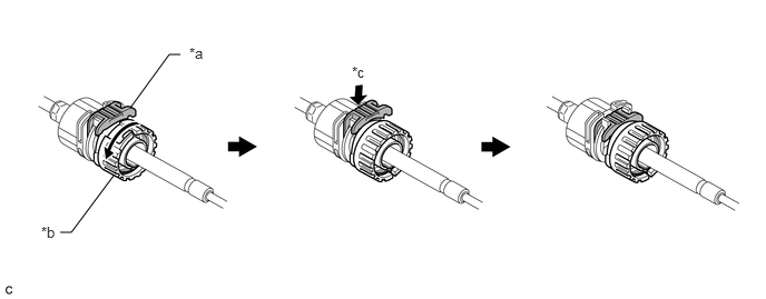
| *a | Stopper | *b | Nut |
| *c | Push in | - | - |
Connect the transmission control cable assembly to the transmission floor shift assembly. Check that the spring is positioned at (A) and push in the stopper.
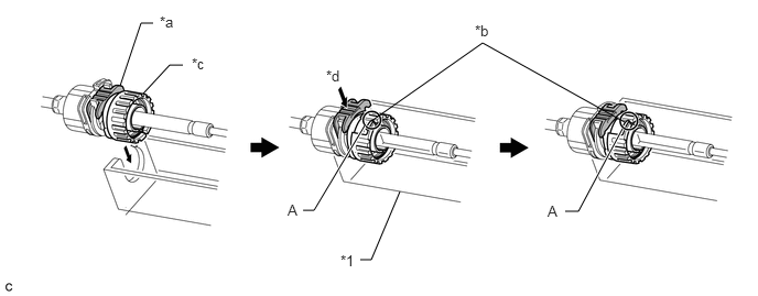
| *1 | Transmission Floor Shift Assembly | - | - |
| *a | Stopper | *b | Spring |
| *c | Nut | *d | Push in |
- NOTICE:
- ·
If the stopper cannot be pushed in, slightly turn the nut clockwise and then push in the stopper again.
·Make sure that the transmission control cable assembly is securely locked.
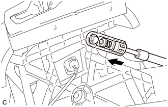
Confirm that the shift lever is in N, and then install the end of the transmission control cable assembly to the transmission floor shift assembly.
- NOTICE:
- ·
Install the end of the transmission control cable assembly all the way to the base of the pin.
·Install the end of the transmission control cable assembly so that its adjustment lock section is on the driver side.
33504F
4.INSTALL SHIFT LEVER KNOB SUB-ASSEMBLY
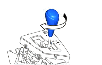
Turn the shift lever knob sub-assembly clockwise to install the shift lever knob sub-assembly.
58910C
5.INSTALL REAR CONSOLE BOX ASSEMBLY
6.INSPECT SHIFT LEVER POSITION
7.ADJUST SHIFT LEVER POSITION