K313 CVT TRANSMISSION CONTROL CABLE ADJUSTMENT
PROCEDURE

 1.ADJUST SHIFT LEVER POSITION
Apply the parking brake and move the shift lever to N.
Remove the rear console box assembly.
Click hereVehicle Interior>INTERIOR PANELS / TRIM>FRONT CONSOLE BOX>REMOVAL
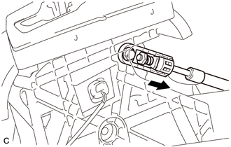
Separate the end of the transmission control cable assembly from the transmission floor shift assembly.
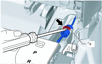
| *a | Stopper |
Using a screwdriver, pull out the stopper of the transmission control cable assembly.
- NOTICE:
-
Do not remove the stopper. If it is removed, reinstall it to its original position.
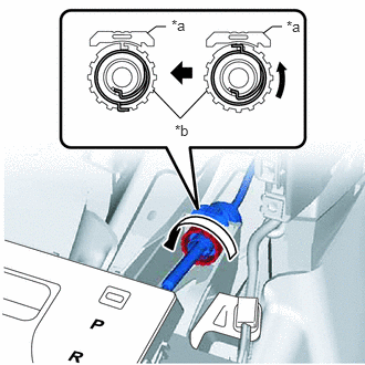
| *a | Stopper |
| *b | Nut |
Turn the nut counterclockwise approximately 180° and, while holding the nut in that position, separate the transmission control cable assembly from the transmission floor shift assembly.
- NOTICE:
-
Do not turn the nut excessively as the internal spring may come off and the transmission control cable assembly will not be reusable.
Push the 2 claws together at the top of the lock piece. While holding the 2 claws together, push the 2 lugs on the bottom of the lock piece toward each other and upward to push up the lock piece.
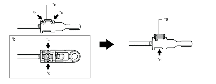
| *a | Lock Piece | *b | Bottom View |
| *c | Push | *d | Push up |
Turn the nut of the transmission control cable assembly counterclockwise approximately 180°. While holding the nut in that position, push in the stopper until it clicks twice.
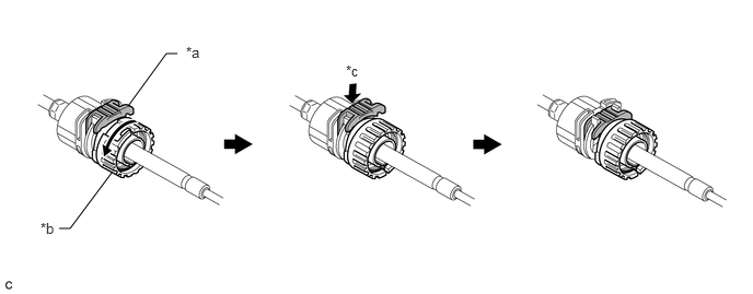
| *a | Stopper | *b | Nut |
| *c | Push in | - | - |
Install the transmission control cable assembly to the transmission floor shift assembly. Check that the spring is positioned at (A) and push in the stopper.
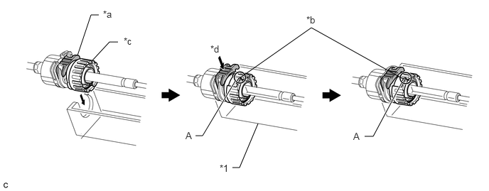
| *1 | Transmission Floor Shift Assembly | - | - |
| *a | Stopper | *b | Spring |
| *c | Nut | *d | Push in |
- NOTICE:
- ·
If the stopper cannot be pushed in, slightly turn the nut clockwise and then push in the stopper again.
·Make sure that the transmission control cable assembly is securely locked.
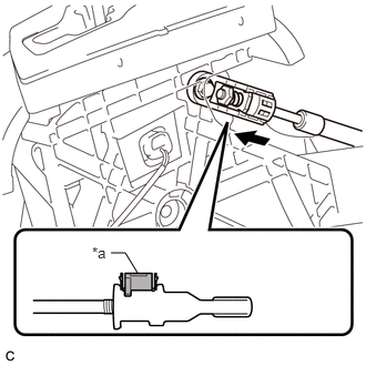
| *a | Lock Piece |
Install the end of the transmission control cable assembly to the transmission floor shift assembly.
- NOTICE:
- ·
Install the end of the transmission control cable assembly all the way to the base of the pin.
·Install the end of the transmission control cable assembly so that its adjustment lock section is on the driver side.
·Check that the lock piece is pulled up.
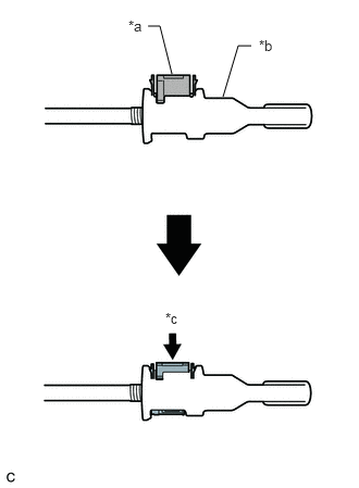
| *a | Lock Piece |
| *b | Adjuster Case |
| *c | Push in |
Push the lock piece into the adjuster case.
- NOTICE:
- ·
Check that the park/neutral position switch assembly and shift lever are in neutral.
·Securely push in the lock piece until the slider lock is engaged.
After adjusting the shift lever position, check the operation and function of the shift lever. If there is a problem, adjust the position again.
Install the rear console box assembly.
Click hereVehicle Interior>INTERIOR PANELS / TRIM>FRONT CONSOLE BOX>INSTALLATION