LIGHTING (EXT) LIGHTING SYSTEM Hazard Warning Switch Circuit
DESCRIPTION
The combination meter assembly receives the hazard warning signal switch assembly ON signal and controls the operation of the hazard warning lights.
WIRING DIAGRAM
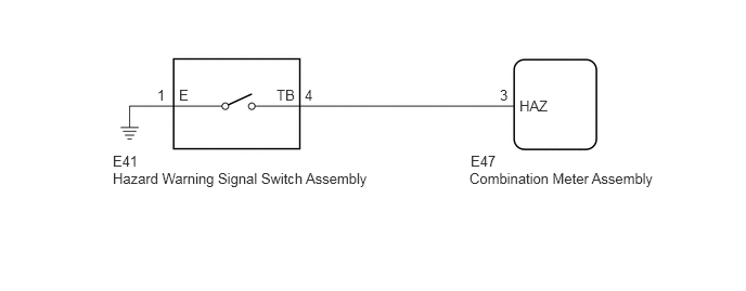
1.083,1.469 1.969,1.635
0.885,0.167
10
false
E41
1.083,1.635 3.635,1.823
2.552,0.188
10
false
Hazard Warning Signal Switch Assembly
4.521,1.469 4.813,1.625
0.292,0.156
10
false
E47
4.51,1.635 6.333,1.813
1.823,0.177
10
false
Combination Meter Assembly
4.99,0.938 5.281,1.094
0.292,0.156
10
false
HAZ
4.802,0.833 4.927,1
0.125,0.167
10
false
3
2.927,0.833 3.052,1
0.125,0.167
10
false
4
2.656,0.833 2.865,1
0.208,0.167
10
false
TB
1.719,0.833 1.854,1
0.135,0.167
10
false
E
1.51,0.833 1.646,1
0.135,0.167
10
false
1
PROCEDURE
1.READ VALUE USING GTS
a.
Connect the GTS to the DLC3.
b.
Turn the ignition switch to ON.
c.
Turn the GTS on.
d.
Enter the following menus: Body Electrical / Combination Meter / Data List.
e.
Read the display on the GTS.
- Body Electrical > Combination Meter > Data List
-
Tester Display Measurement Item Range Normal Condition Diagnostic Note Hazard Flasher Switch Hazard warning signal switch signal ON or OFF ON: Hazard warning signal switch on
OFF: Hazard warning signal switch off-
- Body Electrical > Combination Meter > Data List
-
Tester Display Hazard Flasher Switch - 50003 122 99
- OK:
Normal conditions listed above are displayed.
- Result:
Proceed to OK NG
OK
PROCEED TO NEXT SUSPECTED AREA SHOWN IN PROBLEM SYMPTOMS TABLE
NG
2.INSPECT HAZARD WARNING SIGNAL SWITCH ASSEMBLY
2.INSPECT HAZARD WARNING SIGNAL SWITCH ASSEMBLY
a.
Remove the hazard warning signal switch assembly.
Click hereVehicle Exterior>LIGHTING (EXT)>HAZARD WARNING SWITCH>REMOVAL
b.
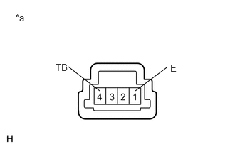
1.979,1.333 2.438,0.99
false
1.458,1.333 1,0.979
false
0.229,0.177 0.51,0.375
0.281,0.198
10
*a
0.813,0.906 1.125,1.104
0.313,0.198
10
TB
2.49,0.917 2.646,1.115
0.156,0.198
10
E
| *a | Component without harness connected
(Hazard Warning Signal Switch Assembly) |
Measure the resistance according to the value(s) in the table below.
- Standard Resistance:
Tester Connection Condition Specified Condition 4 (TB) - 1 (E) Hazard warning signal switch on Below 1 Ω Hazard warning signal switch off 10 kΩ or higher
- Result:
Proceed to OK NG
OK
3.CHECK HARNESS AND CONNECTOR (HAZARD WARNING SIGNAL SWITCH ASSEMBLY - COMBINATION METER ASSEMBLY AND BODY GROUND)
NG
REPLACE HAZARD WARNING SIGNAL SWITCH ASSEMBLY
3.CHECK HARNESS AND CONNECTOR (HAZARD WARNING SIGNAL SWITCH ASSEMBLY - COMBINATION METER ASSEMBLY AND BODY GROUND)
a.
Disconnect the E47 combination meter assembly connector.
b.
Measure the resistance according to the value(s) in the table below.
- Standard Resistance:
Tester Connection Condition Specified Condition E41-4 (TB) - E47-3 (HAZ) Always Below 1 Ω E41-4 (TB) - Body ground Always 10 kΩ or higher E41-1 (E) - Body ground Always Below 1 Ω
- Result:
Proceed to OK NG
OK
REPLACE COMBINATION METER ASSEMBLY
NG
REPAIR OR REPLACE HARNESS OR CONNECTOR