BRAKE CONTROL / DYNAMIC CONTROL SYSTEMS ANTI-LOCK BRAKE SYSTEM ABS Warning Light Remains ON
DESCRIPTION
The skid control ECU (brake actuator assembly) is connected to the combination meter assembly via CAN communication.
If any of the following is detected, the ABS warning light remains on:
The skid control ECU (brake actuator assembly) connector is disconnected from the skid control ECU (brake actuator assembly).
There is a malfunction in the skid control ECU (brake actuator assembly) internal circuit.
There is an open in the harness between the combination meter assembly and the skid control ECU (brake actuator assembly).
The ABS is defective.
- HINT:
-
In some cases, the GTS cannot be used when the skid control ECU (brake actuator assembly) is abnormal.
WIRING DIAGRAM
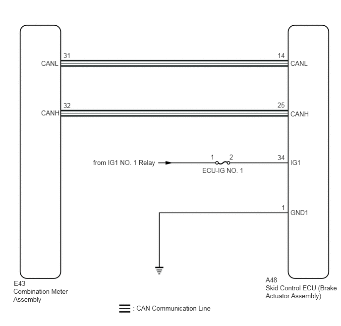
CAUTION / NOTICE / HINT
- NOTICE:
-
Inspect the fuses for circuits related to this system before performing the following procedure.
PROCEDURE
Check if CAN communication system DTCs are output.
Click herePower Source / Network>NETWORKING>CAN COMMUNICATION SYSTEM>DIAGNOSIS SYSTEM
- Result:
Result Proceed to DTCs are not output. A DTCs are output. B
A
B
Click herePower Source / Network>NETWORKING>CAN COMMUNICATION SYSTEM>HOW TO PROCEED WITH TROUBLESHOOTING
Check if the skid control ECU (brake actuator assembly) connector is securely connected.
- OK:
The connector is securely connected.
- Result:
Proceed to OK NG
OK
NG
Check the battery voltage.
- Standard Voltage:
11 to 14 V
- Result:
Proceed to OK NG
OK
NG
for 1ZR-FE: Click herePower Source / Network>1ZR-FE BATTERY / CHARGING>CHARGING SYSTEM>ON-VEHICLE INSPECTION
for 2ZR-FE: Click herePower Source / Network>2ZR-FE BATTERY / CHARGING>CHARGING SYSTEM>ON-VEHICLE INSPECTION
for 2NZ-FE: Click herePower Source / Network>2NZ-FE BATTERY / CHARGING>CHARGING SYSTEM>ON-VEHICLE INSPECTION
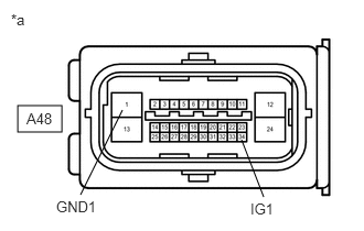
| *a | Front view of wire harness connector
(to Skid Control ECU (Brake Actuator Assembly)) |
Disconnect the A48 skid control ECU (brake actuator assembly) connector.
Measure the voltage according to the value(s) in the table below.
- Standard Voltage:
Tester Connection Condition Specified Condition A48-34 (IG1) - Body ground Ignition switch ON 11 to 14 V A48-34 (IG1) - A48-1 (GND1) Ignition switch ON 11 to 14 V
- Result:
Proceed to OK NG
OK
NG
Turn the ignition switch off.
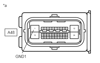
| *a | Front view of wire harness connector
(to Skid Control ECU (Brake Actuator Assembly)) |
Measure the resistance according to the value(s) in the table below.
- Standard Resistance:
Tester Connection Condition Specified Condition A48-1 (GND1) - Body ground Always Below 1 Ω
- Result:
Proceed to OK NG
OK
NG
Reconnect the A48 skid control ECU (brake actuator assembly) connector.
Connect the GTS to the DLC3.
Turn the ignition switch to ON.
Select the Data List on the GTS.
Click hereBrake>BRAKE CONTROL / DYNAMIC CONTROL SYSTEMS>ANTI-LOCK BRAKE SYSTEM>DATA LIST / ACTIVE TEST
- Chassis > ABS/VSC/TRC > Data List
-
Tester Display Measurement Item Range Normal Condition Diagnostic Note ABS Warning Light ABS warning light ON or OFF ON: Warning light on
OFF: Warning light off-
- Chassis > ABS/VSC/TRC > Data List
-
Tester Display ABS Warning Light - 50003 105 51
Check the GTS display condition of the ABS warning light.
- Result:
Result Proceed to Display of the Data List remains ON. A Display of the Data List remains OFF. B
- HINT:
-
If troubleshooting has been carried out according to Problem Symptoms Table, refer back to the table and proceed to the next step before replacing parts.
-
Click hereBrake>BRAKE CONTROL / DYNAMIC CONTROL SYSTEMS>ANTI-LOCK BRAKE SYSTEM>PROBLEM SYMPTOMS TABLE
A
B
Click hereVehicle Interior>METER / GAUGE / DISPLAY>METER / GAUGE SYSTEM>HOW TO PROCEED WITH TROUBLESHOOTING