BRAKE CONTROL / DYNAMIC CONTROL SYSTEMS BRAKE ACTUATOR REMOVAL
PROCEDURE

 1. PRECAUTION
- NOTICE:
-
After turning the ignition switch off, waiting time may be required before disconnecting the cable from the negative (-) battery terminal. Therefore, make sure to read the disconnecting the cable from the negative (-) battery terminal notices before proceeding with work.
-
Click hereGeneral>INTRODUCTION>REPAIR INSTRUCTION>PRECAUTION
2.DISCONNECT CABLE FROM NEGATIVE BATTERY TERMINAL
- NOTICE:
-
When disconnecting the cable, some systems need to be initialized after the cable is reconnected.
-
Click hereGeneral>INTRODUCTION>REPAIR INSTRUCTION>INITIALIZATION
3.DRAIN BRAKE FLUID
- NOTICE:
-
If brake fluid leaks onto any painted surface, immediately wash it off.
4.REMOVE FRONT WHEEL RH
53875A
5.SEPARATE FRONT FENDER LINER RH
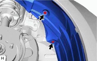
Remove the 2 clips and separate the front fender liner RH.
16471
6.REMOVE RESERVE TANK CAP SUB-ASSEMBLY
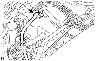
Disengage the clamp to separate the reserve hose.
Remove the reserve tank cap sub-assembly.
16470
7.REMOVE RADIATOR RESERVE TANK ASSEMBLY
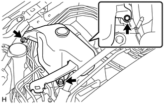
Remove the 3 bolts and radiator reserve tank assembly.
88707
8.SEPARATE SUCTION PIPE SUB-ASSEMBLY
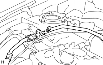
Disengage the clamp to separate the suction pipe sub-assembly.
- NOTICE:
- ·
Do not deform the refrigerant lines.
·Do not damage the clamp.
88710
9.SEPARATE AIR CONDITIONER TUBE ASSEMBLY
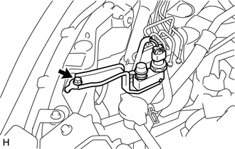
Remove the bolt and separate the bracket.
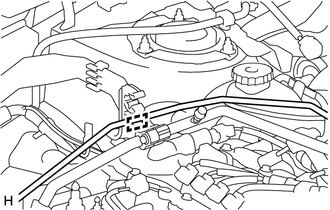
Disengage the clamp to separate the air conditioner tube assembly.
- NOTICE:
- ·
Do not deform the refrigerant lines.
·Do not damage the clamp.
10.REMOVE BRAKE ACTUATOR WITH BRACKET
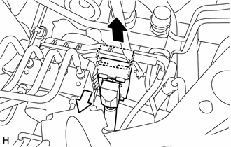

|
Release |

|
Disconnect |
Release the lock lever and disconnect the connector from the brake actuator assembly.
- NOTICE:
-
Be careful not to allow any brake fluid to enter the connector.
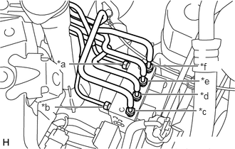
| *a | From 1st Chamber of Master Cylinder Sub-assembly |
| *b | From 2nd Chamber of Master Cylinder Sub-assembly |
| *c | To Front Wheel Cylinder Assembly LH |
| *d | To Rear Wheel Cylinder Assembly RH |
| *e | To Rear Wheel Cylinder Assembly LH |
| *f | To Front Wheel Cylinder Assembly RH |
Use tags or make a memo to identify the places to reconnect the brake lines.
Using a union nut wrench, disconnect the 6 brake lines from the brake actuator assembly.
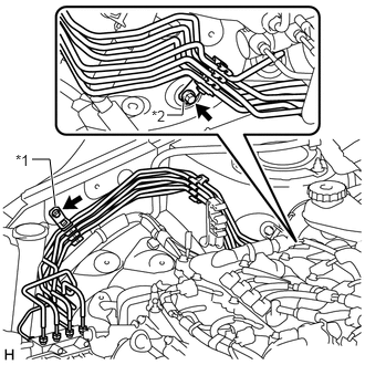
| *1 | No. 2 Brake Tube Clamp Bracket |
| *2 | No. 3 Brake Tube Clamp Bracket |
Remove the 2 bolts and separate the No. 2 brake tube clamp bracket and No. 3 brake tube clamp bracket.
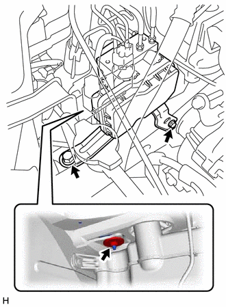
Remove the 2 bolts, nut and brake actuator with bracket.
- NOTICE:
-
Do not damage the brake lines or refrigerant lines.
44510
11.REMOVE BRAKE ACTUATOR ASSEMBLY
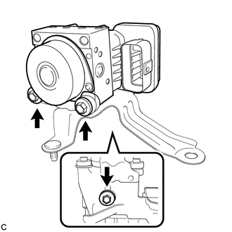
Remove the 3 bolts and brake actuator assembly from the brake actuator bracket assembly.