2NZ-FE ENGINE CONTROL SFI SYSTEM P0134 Oxygen Sensor Circuit No Activity Detected (Bank 1 Sensor 1)
DESCRIPTION
Refer to DTC P0031.
Click hereEngine / Hybrid System>2NZ-FE ENGINE CONTROL>SFI SYSTEM>P0031
| DTC No. | Detection Item | DTC Detection Condition | Trouble Area | MIL | Memory |
|---|---|---|---|---|---|
| P0134 | Oxygen Sensor Circuit No Activity Detected (Bank 1 Sensor 1) | Heated oxygen sensor output does not indicate rich (more than 0.45 V) even once when conditions (a), (b), (c), (d) and (e) continue for more than 50 seconds (1 trip detection logic):
(a) Engine speed: 1400 rpm or more (b) Vehicle speed: 40 km/h (24 mph) or more (c) Throttle valve not fully closed (d) 180 seconds or more after starting engine (e) Engine coolant temperature more than 40°C (104°F) |
·
Open or short in heated oxygen sensor circuit ·
Heated oxygen sensor ·
Fuel pressure ·
Intake system ·
PCV hose connections ·
PCV valve and hose ·
Fuel injector assembly ·
Exhaust gas leakage ·
ECM |
Comes on | DTC stored |
- HINT:
-
If this DTC is stored, check the output voltage of the heated oxygen sensor by entering the following menus on the GTS: Powertrain / Engine and ECT / Data List / All Data / O2S B1S1.
MONITOR DESCRIPTION
The ECM uses the heated oxygen sensor to optimize the air fuel mixture with closed loop fuel control. This control helps decrease exhaust emissions by providing the catalyst with a nearly stoichiometric mixture. The sensor detects the oxygen level in the exhaust gas and the ECM uses this data to control the air fuel ratio. The sensor output voltage range is from 0 V to 1 V. If the signal voltage is less than 0.45 V, the air fuel ratio is lean. If the signal voltage is more than 0.45 V, the air fuel ratio is rich. If the sensor does not indicate rich at least once despite the conditions for the closed loop fuel control being met and the specified time period has passed, the ECM will conclude that the closed loop fuel control is malfunctioning. The ECM will illuminate the MIL and a DTC is stored.
MONITOR STRATEGY
| Required Sensors/Components (Main) | Heated oxygen sensor |
| Required Sensors/Components (Related) | Engine coolant temperature sensor
Throttle body with motor assembly Crankshaft position sensor Vehicle speed sensor |
| Frequency of Operation | Once per driving cycle |
TYPICAL ENABLING CONDITIONS
| Intrusive closed loop is performed when following conditions met | - |
| Duration that the following conditions met | 50 seconds |
| Engine coolant temperature | 40°C (104°F) or higher |
| Engine speed | 1400 rpm or higher |
| Vehicle speed | 40 km/h (24 mph) or higher |
| Idle | OFF |
| Battery voltage | 11 V or higher |
TYPICAL MALFUNCTION THRESHOLDS
| Oxygen sensor voltage | Less than 0.45 V |
CONFIRMATION DRIVING PATTERN

Connect the GTS to the DLC3.
Turn the ignition switch to ON and turn the GTS on.
Clear DTCs (even if no DTCs are stored, perform the clear DTC operation).
Turn the ignition switch off and wait for at least 30 seconds.
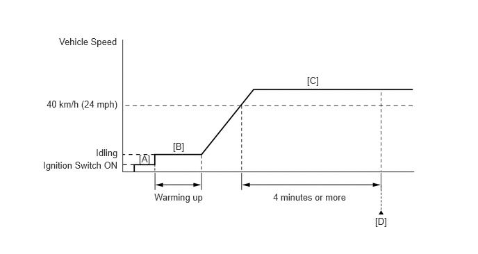
Turn the ignition switch to ON and turn the GTS on [A].
Start the engine and warm it up until the engine coolant temperature reaches 40°C (104°F) or higher [B].
Drive the vehicle at 40 km/h (24 mph) or more for 4 minutes or more [C].
- CAUTION:
-
When performing the confirmation driving pattern, obey all speed limits and traffic laws.
Enter the following menus: Powertrain / Engine and ECT / Trouble Codes [D].
Read the pending DTCs.
- HINT:
- ·
If a pending DTC is output, the system is malfunctioning.
·If a pending DTC is not output, perform the following procedure.
Enter the following menus: Powertrain / Engine and ECT / Utility / All Readiness.
Input the DTC: P0134.
Check the DTC judgment result.
| GTS Display | Description |
|---|---|
| NORMAL | ·
DTC judgment completed ·
System normal |
| ABNORMAL | ·
DTC judgment completed ·
System abnormal |
| INCOMPLETE | ·
DTC judgment not completed ·
Perform driving pattern after confirming DTC enabling conditions |
| N/A | ·
Unable to perform DTC judgment ·
Number of DTCs which do not fulfill DTC preconditions has reached ECU memory limit |
- HINT:
- ·
If the judgment result shows NORMAL, the system is normal.
·If the judgment result shows ABNORMAL, the system has a malfunction.
·If the judgment result shows INCOMPLETE or N/A, perform steps [C] through [D] again.
WIRING DIAGRAM
Refer to DTC P0031.
Click hereEngine / Hybrid System>2NZ-FE ENGINE CONTROL>SFI SYSTEM>P0031
CAUTION / NOTICE / HINT
- HINT:
- ·
Change the fuel injection volume using the Control the Injection Volume for A/F Sensor function provided in the Active Test and monitor the heated oxygen sensor output voltage. If the sensor output voltage does not change (almost no reaction) while performing the Active Test, the sensor may be malfunctioning.
Click hereEngine / Hybrid System>2NZ-FE ENGINE CONTROL>SFI SYSTEM>P0132
·Read freeze frame data using the GTS. Freeze frame data records the engine condition when malfunctions are detected. When troubleshooting, freeze frame data can help determine if the vehicle was moving or stationary, if the engine was warmed up or not, if the air fuel ratio was lean or rich, and other data from the time the malfunction occurred.
PROCEDURE
Connect the GTS to the DLC3.
Turn the ignition switch to ON.
Turn the GTS on.
Enter the following menus: Powertrain / Engine and ECT / Trouble Codes.
Read the DTCs.
- Powertrain > Engine and ECT > Trouble Codes
- 50001 234
- Result:
Result Proceed to DTC P0134 is output A DTC P0134 and other DTCs are output B
- HINT:
-
If any DTCs other than P0134 are output, troubleshoot those DTCs first.
A
B
Connect the GTS to the DLC3.
Turn the ignition switch to ON and turn the GTS on.
Start the engine.
Enter the following menus: Powertrain / Engine and ECT / Data List / Engine Speed and O2S B1S1.
- Powertrain > Engine and ECT > Data List
-
Tester Display Engine Speed O2S B1S1 - 50003 234 9,42
Warm up the engine until the engine coolant temperature reaches higher than 40°C (104°F).
Rev the engine up to 4000 rpm 3 times using the accelerator pedal.
Read the output voltage of the heated oxygen sensor displayed on the GTS when the engine speed is suddenly increased.
- Standard voltage:
Heated oxygen sensor voltage output indicates 0.45 V or higher (rich signal) at least once.
- Result:
Proceed to OK NG
OK
NG
Drive the vehicle in accordance with the driving pattern described in Confirmation Driving Pattern.
- Result:
Proceed to NEXT
NEXT
Connect the GTS to the DLC3.
Turn the ignition switch to ON.
Turn the GTS on.
Enter the following menus: Powertrain / Engine and ECT / Trouble Codes.
Read the DTCs.
- Powertrain > Engine and ECT > Trouble Codes
- 50001 234
- Result:
Result Proceed to DTCs are not output A DTC P0134 is output B
A
B
Has the vehicle run out of fuel in the past?
- Result:
Proceed to YES NO
YES
NO
Inspect the PCV hose connections.
Click hereEngine / Hybrid System>2NZ-FE EMISSION CONTROL>PCV VALVE>COMPONENTS
- OK:
PCV hose is connected correctly and is not damaged.
- Result:
Proceed to OK NG
OK
NG
Inspect the heated oxygen sensor.
Click hereEngine / Hybrid System>2NZ-FE ENGINE CONTROL>HEATED OXYGEN SENSOR>INSPECTION
- Result:
Proceed to OK NG
OK
NG

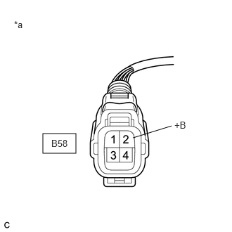
| *a | Front view of wire harness connector
(to Heated Oxygen Sensor) |
Disconnect the heated oxygen sensor connector.
Turn the ignition switch to ON.
Measure the voltage according to the value(s) in the table below.
- Standard Voltage:
Tester Connection Condition Specified Condition B58-2 (+B) - Body ground Ignition switch ON 11 to 14 V
- Result:
Proceed to OK NG
OK
NG
Disconnect the heated oxygen sensor connector.
Disconnect the ECM connector.
Measure the resistance according to the value(s) in the table below.
- Standard Resistance:
Tester Connection Condition Specified Condition B58-1 (HT1A) - B56-109 (HT1A) Always Below 1 Ω B58-3 (OX1A) - B56-112 (OX1A) Always Below 1 Ω B58-4 (E2) - B56-90 (EX1A) Always Below 1 Ω B58-1 (HT1A) or B56-109 (HT1A) - Body ground Always 10 kΩ or higher B58-3 (OX1A) or B56-112 (OX1A) - Body ground Always 10 kΩ or higher B58-4 (E2) or B56-90 (EX1A) - Body ground Always 10 kΩ or higher
- Result:
Proceed to OK NG
OK
NG
Check the intake system for vacuum leaks.
Click hereEngine / Hybrid System>2NZ-FE INTAKE / EXHAUST>INTAKE SYSTEM>ON-VEHICLE INSPECTION
- OK:
No leaks in intake system.
- Result:
Proceed to OK NG
OK
NG
Check the fuel pressure.
Click hereEngine / Hybrid System>2NZ-FE FUEL>FUEL SYSTEM>ON-VEHICLE INSPECTION
- Result:
Proceed to OK NG
OK
NG
Check the fuel injector assembly injection (whether fuel volume is high or low, and whether injection pattern is poor).
Click hereEngine / Hybrid System>2NZ-FE FUEL>FUEL INJECTOR>INSPECTION
- Result:
Proceed to OK NG
OK
NG
Check for exhaust gas leak.
- OK:
No gas leak.
- Result:
Proceed to OK NG
OK
NG