DOOR / HATCH FRONT DOOR REASSEMBLY
CAUTION / NOTICE / HINT
- HINT:
- ·
Use the same procedure for the RH side and LH side.
·The following procedure is for the RH side.
PROCEDURE

 1. PRECAUTION (w/ Power Window)
- NOTICE:
-
After turning the ignition switch off, waiting time may be required before disconnecting the cable from the negative (-) battery terminal. Therefore, make sure to read the disconnecting the cable from the negative (-) battery terminal notices before proceeding with work.
-
Click hereGeneral>INTRODUCTION>REPAIR INSTRUCTION>PRECAUTION
2. REPAIR INSTRUCTION
75921C
3.INSTALL NO. 1 BLACK OUT TAPE
- HINT:
-
Use the same procedure as for the LH side.
-
Click hereVehicle Exterior>EXTERIOR PANELS / TRIM>BLACK OUT TAPE(for Front Door)>INSTALLATION
75755C
4.INSTALL FRONT DOOR REAR WINDOW FRAME MOULDING
- HINT:
-
Use the same procedure as for the LH side.
-
Click hereVehicle Exterior>EXTERIOR PANELS / TRIM>FRONT DOOR WINDOW FRAME MOULDING>INSTALLATION
75710
5.INSTALL FRONT DOOR BELT MOULDING ASSEMBLY
- HINT:
-
Use the same procedure as for the LH side.
-
Click hereVehicle Exterior>EXTERIOR PANELS / TRIM>FRONT DOOR BELT MOULDING>INSTALLATION
67837K
6.INSTALL FRONT DOOR VENT SEAL
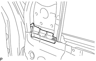
Install the front door vent seal.
67001A
7.INSTALL FRONT DOOR PANEL CUSHION
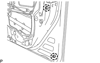
Engage the 2 claws to install 2 new front door panel cushions.
75792
8.INSTALL DOOR WINDOW FRAME MOULDING CLIP
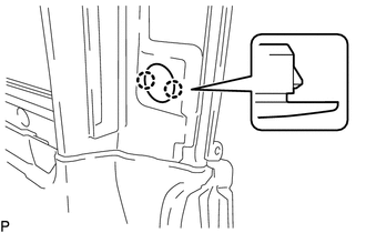
Engage the 2 claws to install a new door window frame moulding clip.
67663D
9.INSTALL DOOR FRAME GARNISH
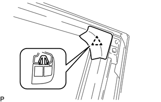
Engage the clip to install a new door frame garnish.
67861
10.INSTALL FRONT DOOR WEATHERSTRIP
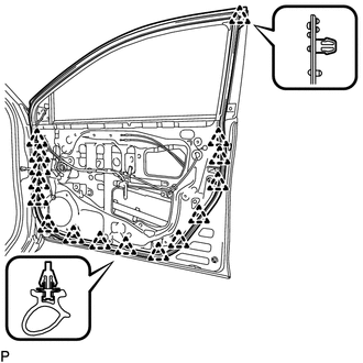
Engage the 16 clips and install the front door weatherstrip.
68610
11.INSTALL FRONT DOOR CHECK ASSEMBLY
Apply MP grease to the sliding areas of the front door check assembly.
Clean the bolt hole on the vehicle body.
Clean the bolt threads of the bolt.
Apply adhesive to the threads of the bolt (A).
- Adhesive:
Toyota Genuine Adhesive 1324, Three Bond 1324 or equivalent
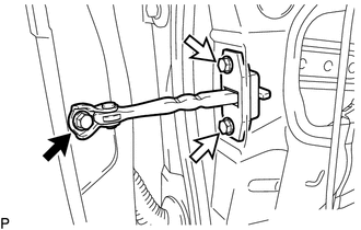

|
Bolt (A) |

|
Bolt (B) |
Install the front door check assembly with the 3 bolts.
- Torque:
- Bolt (A) : 30 N*m (306 kgf*cm, 22 ft.*lbf)
- Bolt (B) : 8.0 N*m (82 kgf*cm, 71 in.*lbf)
69311A
12.INSTALL FRONT DOOR LOCK OPEN ROD
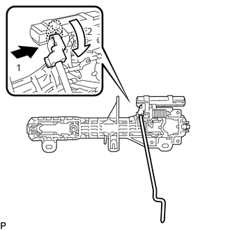
Install the front door lock open rod as indicated by the arrows, in the order shown in the illustration.
69201A
13.INSTALL FRONT DOOR OUTSIDE HANDLE FRAME SUB-ASSEMBLY
Apply MP grease to the sliding parts on the front door outside handle frame sub-assembly.
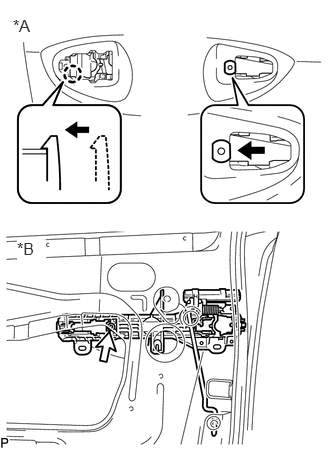
| *A | Outside |
| *B | Inside |
Engage the claw.
Using a T30 "TORX" socket wrench, install the front door outside handle frame sub-assembly with the screw.
- Torque:
- 4.0 N*m (41 kgf*cm, 35 in.*lbf)
w/ Smart Entry and Start System:
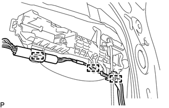
Engage the 3 clamps.
69750C
14.INSTALL FRONT DOOR INSIDE LOCKING CABLE ASSEMBLY
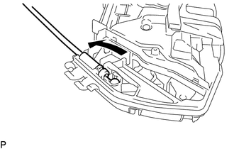
Install the front door inside locking cable assembly as shown in the illustration.
69710B
15.INSTALL FRONT DOOR LOCK REMOTE CONTROL CABLE ASSEMBLY
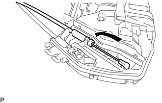
Install the front door lock remote control cable assembly as shown in the illustration.
69035A
16.INSTALL FRONT DOOR LOCK COVER SUB-ASSEMBLY
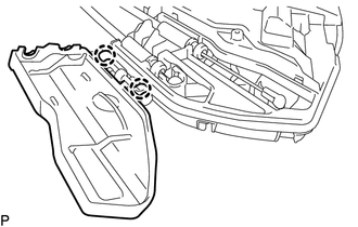
Engage the 2 claws.
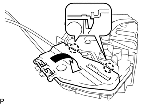
Engage the 2 claws and install the front door lock cover sub-assembly as shown in the illustration.
69310
17.INSTALL FRONT DOOR LOCK ASSEMBLY
- NOTICE:
- ·
When reusing a removed front door lock assembly, replace the door lock wiring harness seal with a new one.
·Do not allow grease or dust to adhere to the door lock wiring harness seal installation surface.
·Reusing a door lock wiring harness seal or using a damaged door lock wiring harness seal may cause water ingress. This may result in a malfunction of the front door lock assembly.
Apply MP grease to the sliding parts of the front door lock assembly.
When reusing the front door lock assembly:
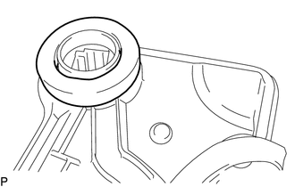
Install a new door lock wiring harness seal to the front door lock assembly.
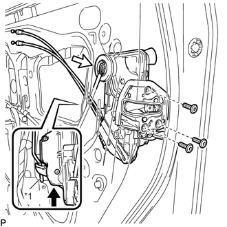
| *1 | Front Door Lock Open Rod |
Connect the front door lock open rod to the front door lock assembly.
- HINT:
-
Make sure that the front door lock open rod is securely connected to the front door lock assembly.
Using a T30 "TORX" socket wrench, install the front door lock assembly with the 3 screws.
- Torque:
- 5.0 N*m (51 kgf*cm, 44 in.*lbf)
Connect the connector.
69242E
18.INSTALL FRONT DOOR REAR OUTSIDE HANDLE PAD
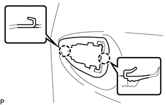
Engage the 2 claws to install the front door rear outside handle pad.
69241H
19.INSTALL FRONT DOOR FRONT OUTSIDE HANDLE PAD
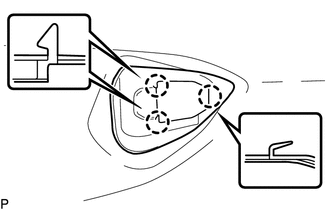
Engage the 3 claws to install the front door front outside handle pad.
69210
20.INSTALL FRONT DOOR OUTSIDE HANDLE ASSEMBLY
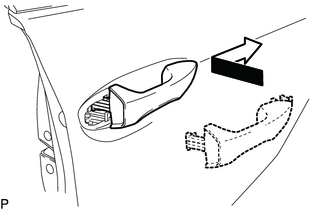
Insert the front end of the front door outside handle assembly into the front door outside handle frame sub-assembly.
Insert the rear end of the front door outside handle assembly into the front door outside handle frame sub-assembly, then slide the front door outside handle assembly toward the front of the vehicle to install it.
w/ Smart Entry and Start System:
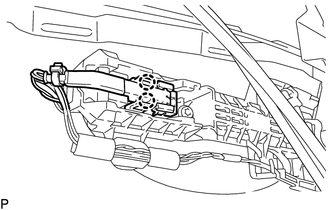
Connect the connector.
Engage the 2 claws.
69217E
21.INSTALL FRONT DOOR OUTSIDE HANDLE COVER RH (for Driver Side)
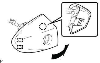
Engage the 2 guides and claw to install the front door outside handle cover RH to the lock cylinder assembly as shown in the illustration.
69217F
22.INSTALL FRONT DOOR OUTSIDE HANDLE COVER LH (for Front Passenger Side)
w/o Lock Cylinder:
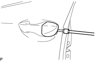
Using a T30 "TORX" socket wrench, install the front door outside handle cover LH with the screw.
- Torque:
- 4.0 N*m (41 kgf*cm, 35 in.*lbf)
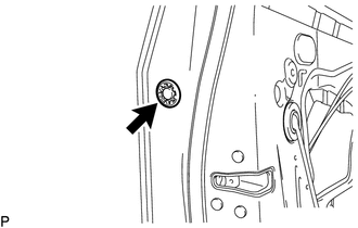
Install the hole plug.
w/ Lock Cylinder:
- HINT:
-
Use the same procedures as for the driver side.
23.INSTALL FRONT DOOR OUTSIDE HANDLE COVER WITH LOCK CYLINDER ASSEMBLY (for Driver Side)
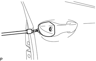
Using a T30 "TORX" socket wrench, install the front door outside handle cover with lock cylinder assembly with the screw.
- Torque:
- 4.0 N*m (41 kgf*cm, 35 in.*lbf)
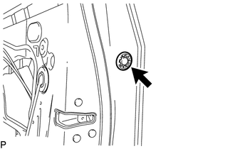
Install the hole plug.
24.INSTALL FRONT DOOR OUTSIDE HANDLE COVER WITH LOCK CYLINDER ASSEMBLY (for Front Passenger Side)
w/ Lock Cylinder:
- HINT:
-
Use the same procedures as for the driver side.
67403F
25.INSTALL FRONT DOOR REAR LOWER FRAME SUB-ASSEMBLY
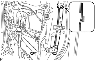
Engage the guide.
Install the front door rear lower frame sub-assembly with the bolt.
- Torque:
- 6.1 N*m (62 kgf*cm, 54 in.*lbf)
68141C
26.INSTALL FRONT DOOR GLASS RUN
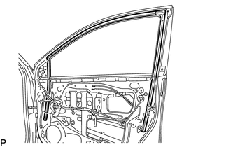
Install the front door glass run.
69820
27.INSTALL FRONT DOOR WINDOW REGULATOR ASSEMBLY (w/o Power Window)
Apply MP grease to the sliding parts of the front door window regulator assembly.
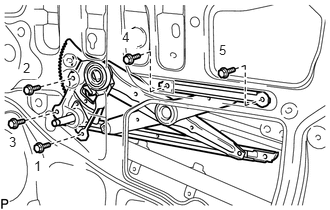
Install the front door window regulator assembly with the 5 bolts.
- HINT:
-
Tighten the bolts in the order shown in the illustration.
- Torque:
- 8.0 N*m (82 kgf*cm, 71 in.*lbf)
85710E
28.INSTALL FRONT POWER WINDOW REGULATOR MOTOR ASSEMBLY (w/ Power Window)
- NOTICE:
-
The regulator arm must be below the intermediate position when installing the front power window regulator motor assembly.
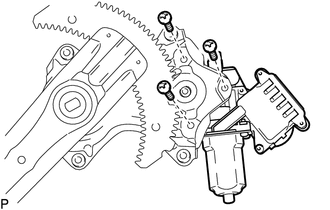
Using a T25 "TORX" socket wrench, install the front power window regulator motor assembly with the 3 screws to front door window regulator sub-assembly.
- Torque:
- 5.4 N*m (55 kgf*cm, 48 in.*lbf)
- HINT:
-
When replacing a front power window regulator motor assembly, a new front power window regulator motor assembly uses self-tapping screws to thread new installation holes when the self-tapping screws are inserted.
29.INSTALL FRONT DOOR WINDOW REGULATOR ASSEMBLY (w/ Power Window)
Apply MP grease to the sliding parts of the front door window regulator assembly.
Temporarily install the temporary bolt to the front door window regulator assembly.
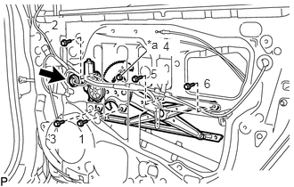
| *a | Temporary Bolt |
Temporarily install the front door window regulator assembly with the 5 bolts.
Tighten the temporary bolt and 5 bolts to install the front door window regulator assembly.
- HINT:
-
Tighten the bolts in the order shown in the illustration.
- Torque:
- 8.0 N*m (82 kgf*cm, 71 in.*lbf)
Connect the connector.
68101
30.INSTALL FRONT DOOR GLASS SUB-ASSEMBLY
w/ Power Window:
Connect the cable to the negative (-) battery terminal.
for Driver Side with Power Window:
Connect the power window regulator master switch assembly and move the front door glass sub-assembly so that the door glass bolts can be seen.
for Front Passenger Side with Power Window:
Connect the power window regulator switch assembly and move the front door glass sub-assembly so that the door glass bolts can be seen.
w/ Power Window:
Disconnect the cable from the negative (-) battery terminal.
for Driver Side with Power Window:
Disconnect the power window regulator master switch assembly.
for Front Passenger Side with Power Window:
Disconnect the power window regulator switch assembly.
w/o Power Window:
Temporarily install the front door window regulator handle assembly and move the front door glass sub-assembly so that the door glass bolts can be seen.
Remove the front door window regulator handle assembly.
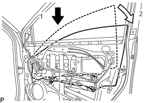
Insert the front door glass sub-assembly into the front door panel along the front door glass run as indicated by the arrows, in the order shown in the illustration.
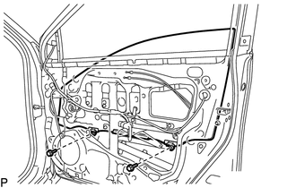
Install the front door glass sub-assembly with the 2 bolts.
- Torque:
- 8.0 N*m (82 kgf*cm, 71 in.*lbf)
67831
31.INSTALL FRONT DOOR SERVICE HOLE COVER
Apply new butyl tape to the front door panel.
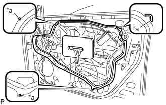
| *a | Reference Point |
Pass the front door lock remote control cable assembly, front door inside locking cable assembly and each connector through a new front door service hole cover.
Install the front door service hole cover according to the reference points on the front door panel.
- NOTICE:
-
Securely install the front door service hole cover preventing wrinkles and air bubbles.
32.INSTALL OUTER REAR VIEW MIRROR ASSEMBLY WITH COVER
68171B
33.INSTALL FRONT DOOR INNER GLASS WEATHERSTRIP
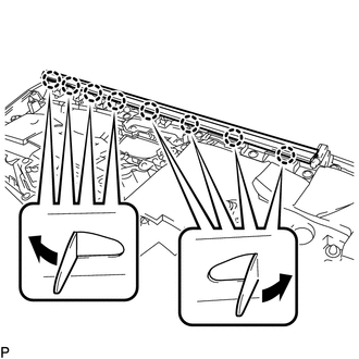
Engage the 8 claws to install the front door inner glass weatherstrip as shown in the illustration.
69205
34.INSTALL FRONT DOOR INSIDE HANDLE SUB-ASSEMBLY
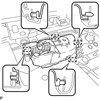
Engage the 4 guides to install the front door inside handle sub-assembly to the front door trim board sub-assembly.
67601
35.INSTALL FRONT DOOR TRIM BOARD SUB-ASSEMBLY
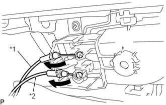
| *1 | Front Door Inside Locking Cable Assembly |
| *2 | Front Door Lock Remote Control Cable Assembly |
Connect the front door lock remote control cable assembly and front door inside locking cable assembly.
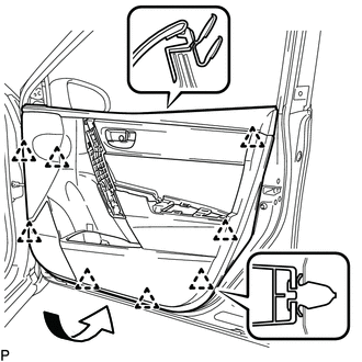
Engage the 8 clips and install the front door trim board sub-assembly as shown in the illustration.
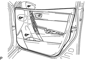
Install the 3 screws.
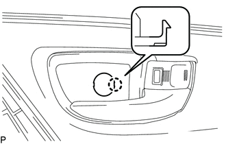
Engage the claw and close the cover.
67491A
36.INSTALL FRONT DOOR LOWER FRAME BRACKET GARNISH
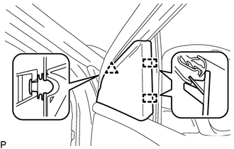
Engage the 2 guides and clip to install the front door lower frame bracket garnish.
69272
37.INSTALL FRONT DOOR REGULATOR INSIDE HANDLE PLATE (w/o Power Window)
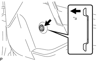
| *a | Inside of vehicle |
Install the front door regulator inside handle plate.
69260
38.INSTALL FRONT DOOR WINDOW REGULATOR HANDLE ASSEMBLY (w/o Power Window)
Temporarily install the front door window regulator handle assembly.
Fully close the front door window.
Remove the front door window regulator handle assembly.
Install the front door window regulator handle shaft snap ring to the front door window regulator handle assembly.
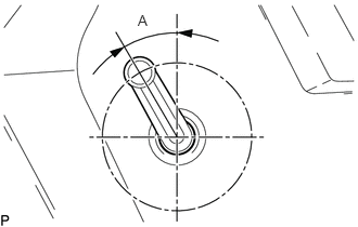
Install the front door window regulator handle assembly with front door window regulator handle shaft snap ring at the angle shown in the illustration.
| Area | Measurement |
|---|---|
| A | 25° to 35° |
39.INSTALL POWER WINDOW REGULATOR MASTER SWITCH ASSEMBLY WITH FRONT DOOR ARMREST BASE PANEL (for Driver Side with Power Window)
Connect the connector.
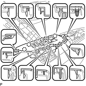
Engage the 4 guides, 8 claws and clip to install the power window regulator master switch assembly with front door armrest base panel.
40.INSTALL POWER WINDOW REGULATOR SWITCH ASSEMBLY WITH FRONT DOOR ARMREST BASE PANEL (for Front Passenger Side with Power Window)
Connect the connector.
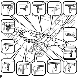
Engage the 5 guides, 8 claws and clip to install the power window regulator switch assembly with front door armrest base panel.
74210
41.INSTALL FRONT ARMREST ASSEMBLY
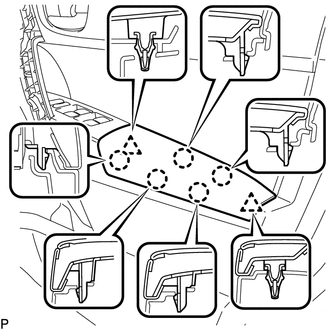
Engage the 5 claws and 2 clips to install the front armrest assembly.
74645A
42.INSTALL DOOR ASSIST GRIP COVER
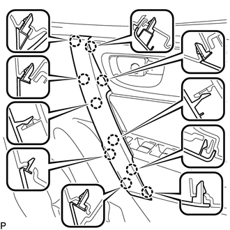
Engage the 10 claws to install the door assist grip cover.
43.CONNECT CABLE TO NEGATIVE BATTERY TERMINAL (w/ Power Window)
- NOTICE:
-
When disconnecting the cable, some systems need to be initialized after the cable is reconnected.
-
Click hereGeneral>INTRODUCTION>REPAIR INSTRUCTION>INITIALIZATION
44.INITIALIZE POWER WINDOW CONTROL SYSTEM (w/ Power Window)
45.INSPECT POWER WINDOW OPERATION (w/ Power Window)