INTERIOR PANELS / TRIM UPPER INSTRUMENT PANEL REASSEMBLY
PROCEDURE

 55981
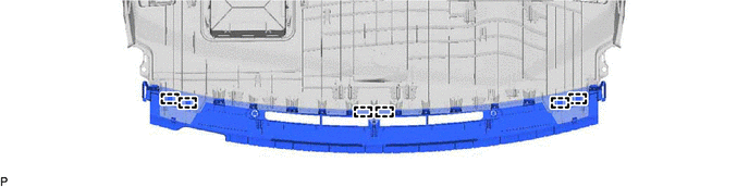
1.INSTALL NO. 1 DEFROSTER NOZZLE GARNISH
Engage the 6 guides.
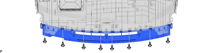
Install the No. 1 defroster nozzle garnish with the 8 screws <B>.
55961A
2.INSTALL SIDE DEFROSTER NOZZLE RH
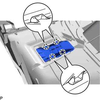
Engage the 4 claws to install the side defroster nozzle RH.
55962A
3.INSTALL SIDE DEFROSTER NOZZLE LH
- HINT:
-
Use the same procedure as for the RH side.
55355
4.INSTALL NO. 1 INSTRUMENT PANEL CUSHION
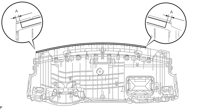
Install a new No. 1 instrument panel cushion as shown in the illustration.
- HINT:
-
Install the ends of the No. 1 instrument panel cushion so that they are within the standard dimension (A) shown in the illustration.
Standard Dimension Area Dimension A 0 to 10 mm (0 to 0.394 in.)
Install a new No. 1 instrument panel cushion as shown in the illustration.
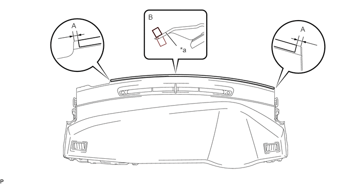
| *a | Alignment Mark | - | - |
- HINT:
- ·
Install the ends of the No. 1 instrument panel cushion so that they are within the standard dimension (A) shown in the illustration.
·Install the No. 1 instrument panel cushion between the alignment mark and the edge of the upper instrument panel assembly (B).
Standard Dimension Area Dimension A 0 to 10 mm (0 to 0.394 in.)
82142
5.INSTALL NO. 2 INSTRUMENT PANEL WIRE (for Manual Air Conditioning System)
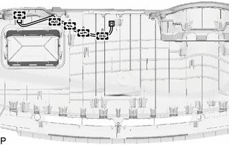
Engage the 5 clamps to install the No. 2 instrument panel wire.
82142
6.INSTALL NO. 2 INSTRUMENT PANEL WIRE (for Automatic Air Conditioning System)
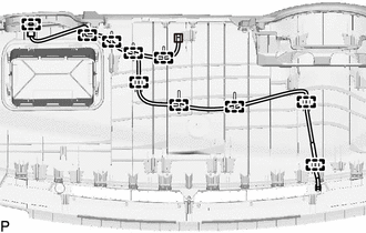
Engage the 10 clamps to install the No. 2 instrument panel wire.
55356C
7.INSTALL NO. 2 INSTRUMENT PANEL CUSHION
Install a new No. 2 instrument panel cushion as shown in the illustration.
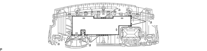
| *a | Marking | - | - |
- HINT:
-
Install the No. 2 instrument panel cushion so that it is within the markings as shown in the illustration.
55416A
8.INSTALL NO. 1 METER HOOD RETAINER
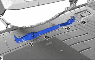
Install the No. 1 meter hood retainer with the 4 screws <B>.
55670A
9.INSTALL CENTER INSTRUMENT PANEL REGISTER ASSEMBLY
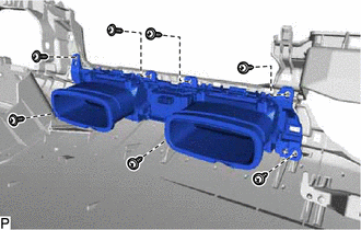
Install the center instrument panel register assembly with the 7 screws <B>.
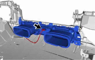
Connect the connector.
88625H
10.INSTALL COOLER (SOLAR SENSOR) THERMISTOR (for Automatic Air Conditioning System)
73960A
11.INSTALL INSTRUMENT PANEL PASSENGER AIRBAG ASSEMBLY
55085
12.INSTALL NO. 2 HEATER TO REGISTER DUCT SUB-ASSEMBLY
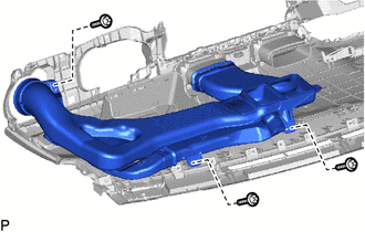
Install the No. 2 heater to register duct sub-assembly with the 3 screws <B>.
55084E
13.INSTALL NO. 1 HEATER TO REGISTER DUCT SUB-ASSEMBLY
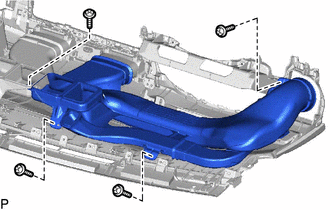
Install the No. 1 heater to register duct sub-assembly with the 4 screws <B>.
55950G
14.INSTALL DEFROSTER NOZZLE ASSEMBLY
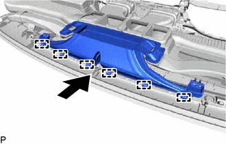
Engage the 6 guides as shown in the illustration.
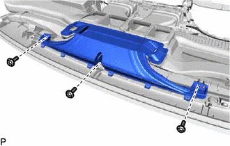
Install the defroster nozzle assembly with the 3 screws <B>.