BRAKE CONTROL / DYNAMIC CONTROL SYSTEMS STEERING ANGLE SENSOR INSTALLATION
CAUTION / NOTICE / HINT
- NOTICE:
-
A lock pin is installed to a new steering sensor. Do not remove the lock pin before the steering sensor is installed to the spiral cable sub-assembly.
PROCEDURE

 84306
1.INSPECT SPIRAL CABLE SUB-ASSEMBLY
84306
1.INSPECT SPIRAL CABLE SUB-ASSEMBLY
89245B
2.INSTALL STEERING SENSOR
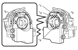
| *a | Guide |
| *b | Pin |
| *c | Lock Pin |
Align the 2 pins and 2 guides, and engage the 6 claws to install the steering sensor to the spiral cable sub-assembly.
- NOTICE:
- ·
Do not remove the lock pin before the steering sensor is installed to the spiral cable sub-assembly.
·Do not damage the pins of the spiral cable sub-assembly and guides of the steering sensor.
·The spiral cable sub-assembly can be rotated up to 30° even when the interlock is engaged. Therefore, make sure that both guides are aligned properly when installing the steering sensor to the spiral cable sub-assembly.
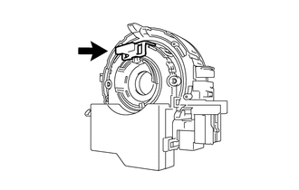
Remove the lock pin from the steering sensor.
84307
3.INSTALL SPIRAL CABLE WITH SENSOR SUB-ASSEMBLY