2ZR-FE ENGINE CONTROL SFI SYSTEM P0660 Intake Manifold Tuning Valve Control Circuit / Open (Bank 1)
DESCRIPTION
This circuit opens and closes the Intake Air Control Valve (IACV) in response to changes in the engine load in order to increase the intake efficiency (ACIS: Acoustic Control Induction System).
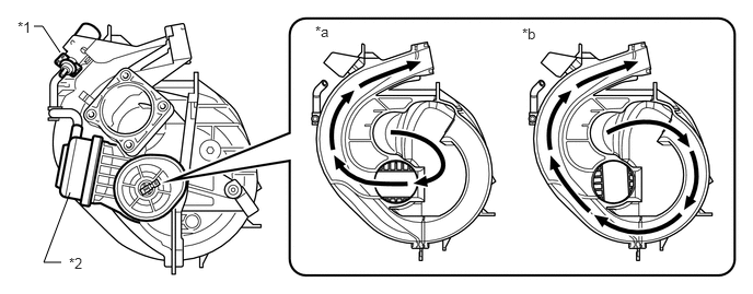
| *1 | Duty Vacuum Switching Valve (for Acoustic Control Induction System) | *2 | Intake Air Control Valve |
| *a | Intake Air Control Valve Open | *b | Intake Air Control Valve Closed |
| DTC No. | Detection Item | DTC Detection Condition | Trouble Area | MIL | Memory |
|---|---|---|---|---|---|
| P0660 | Intake Manifold Tuning Valve Control Circuit / Open (Bank 1) | Open or short in duty vacuum switching valve (for acoustic control induction system) circuit for 0.5 seconds or more (2 trip detection logic) | ·
Open or short in duty vacuum switching valve (for acoustic control induction system) circuit ·
Duty vacuum switching valve (for acoustic control induction system) ·
ECM |
Comes on | DTC stored |
WIRING DIAGRAM
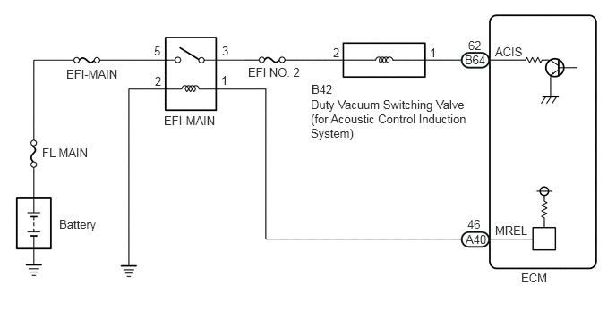
CAUTION / NOTICE / HINT
- NOTICE:
-
Inspect the fuses for circuits related to this system before performing the following procedure.
- HINT:
-
Read freeze frame data using the GTS. The ECM records vehicle and driving condition information as freeze frame data the moment a DTC is stored. When troubleshooting, freeze frame data can help determine if the vehicle was moving or stationary, if the engine was warmed up or not, if the air fuel ratio was lean or rich, and other data from the time the malfunction occurred.
PROCEDURE
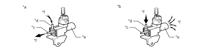
| *a | Duty Vacuum Switching Valve (for Acoustic Control Induction System) is ON | *b | Duty Vacuum Switching Valve (for Acoustic Control Induction System) is OFF |
| *c | Port F | *d | Port E |
| *e | Air Filter | *f | Air |
Disconnect the vacuum hose from the duty vacuum switching valve (for acoustic control induction system).
Connect the GTS to the DLC3.
Turn the ignition switch to ON.
Turn the GTS on.
Enter the following menus: Powertrain / Engine and ECT / Active Test / Activate the VSV for Intake Control.
- Powertrain > Engine and ECT > Active Test
-
Tester Display Activate the VSV for Intake Control - 50004 234 3
Operate the duty vacuum switching valve (for acoustic control induction system).
Check the duty vacuum switching valve (for acoustic control induction system) air flow when switching the duty vacuum switching valve (for acoustic control induction system).
- OK:
Activate the VSV for Intake Control Specified Condition ON Air from port E flows out through port F OFF Air from port E flows out through air filter
- Result:
Proceed to OK NG
OK
NG
Inspect the duty vacuum switching valve (for acoustic control induction system).
Click hereEngine / Hybrid System>2ZR-FE INTAKE / EXHAUST>VACUUM SWITCHING VALVE(for ACIS)>INSPECTION
- Result:
Proceed to OK NG
OK
NG
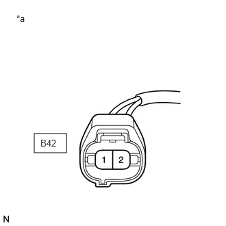
| *a | Front view of wire harness connector
(to Duty Vacuum Switching Valve (for Acoustic Control Induction System)) |
Disconnect the duty vacuum switching valve (for acoustic control induction system) connector.
Turn the ignition switch to ON.
Measure the voltage according to the value(s) in the table below.
- Standard Voltage:
Tester Connection Condition Specified Condition B42-2 - Body ground Ignition switch ON 11 to 14 V
- Result:
Proceed to OK NG
OK
NG
Disconnect the duty vacuum switching valve (for acoustic control induction system) connector.
Disconnect the ECM connector.
Measure the resistance according to the value(s) in the table below.
- Standard Resistance:
Tester Connection Condition Specified Condition B42-1 - B64-62 (ACIS) Always Below 1 Ω B42-1 or B64-62 (ACIS) - Body ground and other terminals Always 10 kΩ or higher
- Result:
Proceed to OK NG
OK
NG