2ZR-FE ENGINE CONTROL  SFI SYSTEM  P0617  Starter Relay Circuit High  


MONITOR DESCRIPTION

While the engine is being cranked, battery voltage is applied to terminal STA of the ECM.

If the ECM detects the starter control (STA) signal while the vehicle is being driven, it determines that there is a malfunction in the STA circuit. The ECM then illuminates the MIL and stores this DTC.

This monitor runs when the vehicle is driven at 20 km/h (12.43 mph) or more for 20 seconds or more.

DTC No. Detection Item DTC Detection Condition Trouble Area MIL Memory
P0617 Starter Relay Circuit High All of the following conditions are met, and a (+B) battery voltage of 10.5 V or higher is applied to the ECM for 20 seconds (1 trip detection logic):

(a) The vehicle speed is 20 km/h (12.43 mph) or more.

(b) The engine speed is 1000 rpm or higher.

(c) The STA signal is on.


·

Park/Neutral position switch assembly*1

·

Ignition switch assembly*2

·

ST NO. 1 relay circuit

·

Certification ECU (smart key ECU assembly)*3

·

ECM


Comes on DTC stored

*1: for CVT Models.

*2: for M/T Models without Smart Entry and Start System.

*3: w/ Smart Entry and Start System.

MONITOR STRATEGY

Required Sensors/Components (Main) ST NO. 1 relay
Ignition switch assembly
Park/Neutral position switch assembly
Certification ECU (smart key ECU assembly)
Required Sensors/Components (Related) Vehicle speed sensor
Crankshaft position sensor
Frequency of Operation Continuous

TYPICAL ENABLING CONDITIONS

Vehicle speed 20 km/h (12.43 mph) or more
Engine speed 1000 rpm or higher

TYPICAL MALFUNCTION THRESHOLDS

Starter signal On

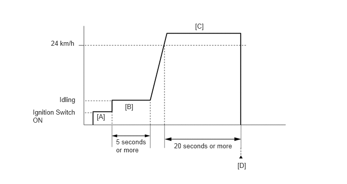
CONFIRMATION DRIVING PATTERN

A231469E36
1.229,1.979 1.604,2.156 0.375,0.177 10 false Idling 0.677,2.24 1.656,2.563 0.979,0.323 10 false Ignition Switch ON 1.052,0.813 1.646,1.042 0.594,0.229 10 false 24 km/h 2.396,2.854 3.083,3.167 0.688,0.313 10 false 5 seconds or more 3.594,2.938 4.865,3.104 1.271,0.167 10 false 20 seconds or more 2,2.333 2.406,2.521 0.406,0.188 10 false [A] 2.583,2.125 2.792,2.302 0.208,0.177 10 false [B] 4.031,0.458 4.26,0.625 0.229,0.167 10 false [C] 4.906,3.344 5.135,3.51 0.229,0.167 10 false [D]

1.

Connect the GTS to the DLC3.

2.

Turn the ignition switch to ON and turn the GTS on.

3.

Clear the DTCs (even if no DTCs are stored, perform the clear DTC procedure).

4.

Turn the ignition switch off and wait for at least 30 seconds.

5.

Turn the ignition switch to ON and turn the GTS on [A].

6.

Start the engine.

7.

Idle the engine for 5 seconds or more [B].

8.

Drive the vehicle at 24 km/h (15 mph) or more for 20 seconds or more [C].

CAUTION:

When performing the confirmation driving pattern, obey all speed limits and traffic laws.


9.

Enter the following menus: Powertrain / Engine and ECT / Trouble Codes [D].

10.

Read the pending DTCs.

HINT:
·

If a pending DTC is output, the system is malfunctioning.

·

If a pending DTC is not output, perform the following procedure.


11.

Enter the following menus: Powertrain / Engine and ECT / Utility / All Readiness.

12.

Input the DTC: P0617.

13.

Check the DTC judgment result.

GTS Display Description
NORMAL
·

DTC judgment completed

·

System normal


ABNORMAL
·

DTC judgment completed

·

System abnormal


INCOMPLETE
·

DTC judgment not completed

·

Perform driving pattern after confirming DTC enabling conditions


N/A
·

Unable to perform DTC judgment

·

Number of DTCs which do not fulfill DTC preconditions has reached ECU memory limit


HINT:
·

If the judgment result shows NORMAL, the system is normal.

·

If the judgment result shows ABNORMAL, the system has a malfunction.

·

If the judgment result shows INCOMPLETE or N/A, perform steps [C] and [D] again and, if necessary, extend the driving time.


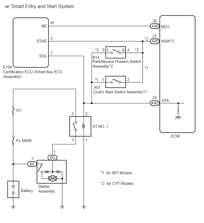
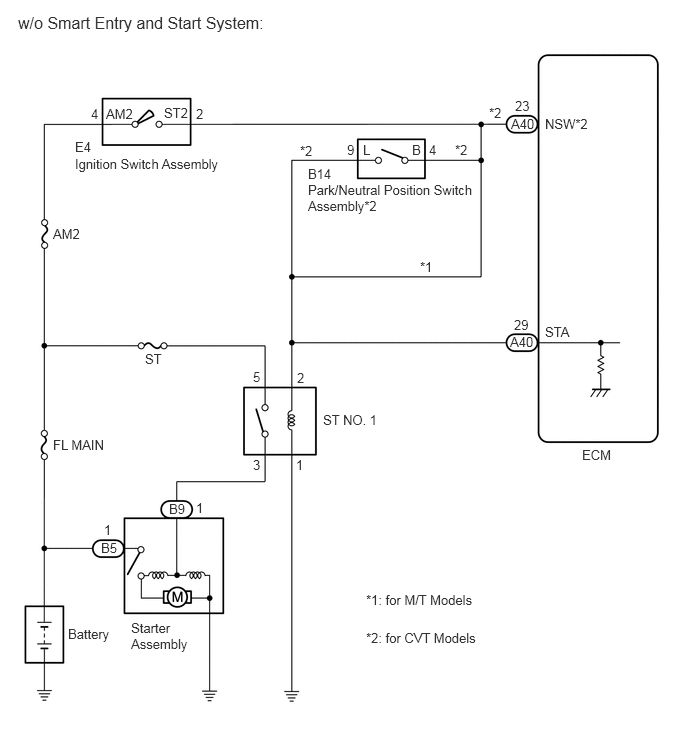
WIRING DIAGRAM
A322472E07
0.188,0.135 2.771,0.406 2.583,0.271 12 false w/o Smart Entry and Start System: 1.104,1.104 1.563,1.302 0.458,0.198 10 false AM2 1.708,1.094 2.167,1.292 0.458,0.198 10 false ST2 5.677,1.208 6.219,1.406 0.542,0.198 10 false NSW*2 6.063,4.656 6.604,4.854 0.542,0.198 10 false ECM 5.323,1.208 5.865,1.406 0.542,0.198 10 false A40 5.313,3.479 5.854,3.677 0.542,0.198 10 false A40 5.365,1.021 5.906,1.219 0.542,0.198 10 false 23 5.354,3.302 5.896,3.5 0.542,0.198 10 false 29 5.677,3.375 6.219,3.573 0.542,0.198 10 false STA 5.094,1.094 5.354,1.313 0.26,0.219 10 false *2 4.74,1.479 5,1.698 0.26,0.219 10 false *2 3.125,1.49 3.385,1.708 0.26,0.219 10 false *2 4.375,2.698 4.635,2.917 0.26,0.219 10 false *1 4.469,1.479 4.729,1.698 0.26,0.219 10 false 4 3.615,1.479 3.875,1.698 0.26,0.219 10 false 9 2.042,1.104 2.302,1.323 0.26,0.219 10 false 2 0.948,1.104 1.208,1.323 0.26,0.219 10 false 4 3.094,3.854 3.354,4.073 0.26,0.219 10 false 2 3.083,4.76 3.344,4.979 0.26,0.219 10 false 1 2.635,4.76 2.896,4.979 0.26,0.219 10 false 3 2.635,3.844 2.896,4.063 0.26,0.219 10 false 5 2.042,5.208 2.302,5.427 0.26,0.219 10 false 1 1.083,5.438 1.344,5.656 0.26,0.219 10 false 1 1.76,5.219 2.031,5.438 0.271,0.219 10 false B9 1.052,5.625 1.323,5.844 0.271,0.219 10 false B5 0.552,2.354 1.01,2.552 0.458,0.198 10 false AM2 1.51,3.656 1.969,3.854 0.458,0.198 10 false ST 0.552,4.552 1.292,4.76 0.74,0.208 10 false FL MAIN 3.365,4.292 4.156,4.521 0.792,0.229 10 false ST NO. 1 0.708,6.521 1.323,6.771 0.615,0.25 10 false Battery 1.365,6.458 2.042,6.865 0.677,0.406 10 false Starter Assembly 3.208,1.729 3.573,1.927 0.365,0.198 10 false B14 3.208,1.896 5.031,2.25 1.823,0.354 10 false Park/Neutral Position Switch Assembly*2 0.781,1.448 1.146,1.646 0.365,0.198 10 false E4 0.781,1.625 2.552,1.865 1.771,0.24 10 false Ignition Switch Assembly 3.813,6.167 6.635,6.406 2.823,0.24 10 false *1: for M/T Models 3.813,6.563 6.719,6.802 2.906,0.24 10 false *2: for CVT Models 3.781,1.479 4.042,1.698 0.26,0.219 10 false L 4.292,1.479 4.552,1.698 0.26,0.219 10 false B

A298561E33
0.177,0.115 2.885,0.479 2.708,0.365 12 false w/ Smart Entry and Start System: 1.458,0.833 1.771,1.031 0.313,0.198 10 false NE 1.281,1.365 1.792,1.573 0.51,0.208 10 false STAR 1.375,1.896 1.885,2.104 0.51,0.208 10 false STA 0.104,2.281 0.615,2.49 0.51,0.208 10 false E108 0.115,2.448 2.271,2.823 2.156,0.375 10 false Certification ECU (Smart Key ECU Assembly) 1.771,1.792 2.083,1.99 0.313,0.198 10 false 7 1.781,1.271 2.094,1.469 0.313,0.198 10 false 5 1.75,0.719 2.063,0.917 0.313,0.198 10 false 16 3.344,1.677 3.656,1.875 0.313,0.198 10 false *2 4.74,1.677 5.052,1.875 0.313,0.198 10 false *2 4.469,1.677 4.781,1.875 0.313,0.198 10 false 4 3.594,1.677 3.906,1.875 0.313,0.198 10 false 9 3.25,1.938 3.76,2.146 0.51,0.208 10 false B14 3.25,2.083 5.01,2.458 1.76,0.375 10 false Park/Neutral Position Switch Assembly*2 5.083,2.313 5.396,2.51 0.313,0.198 10 false *1 3.323,2.729 3.635,2.927 0.313,0.198 10 false *1 3.583,2.729 3.896,2.927 0.313,0.198 10 false 1 4.469,2.719 4.781,2.917 0.313,0.198 10 false 2 3.292,3 3.802,3.208 0.51,0.208 10 false A57 3.271,3.156 5.333,3.365 2.063,0.208 10 false Clutch Start Switch Assembly*1 5.656,0.854 5.969,1.052 0.313,0.198 10 false NEO 5.354,0.656 5.667,0.854 0.313,0.198 10 false 30 5.323,0.833 5.635,1.031 0.313,0.198 10 false A40 5.323,1.365 5.635,1.563 0.313,0.198 10 false A40 5.354,1.188 5.667,1.385 0.313,0.198 10 false 23 5.667,1.365 6.292,1.573 0.625,0.208 10 false NSW*2 5.083,1.292 5.396,1.49 0.313,0.198 10 false *2 5.313,3.552 5.625,3.75 0.313,0.198 10 false A40 5.354,3.365 5.667,3.563 0.313,0.198 10 false 29 5.677,3.458 5.99,3.656 0.313,0.198 10 false STA 6.01,4.719 6.479,4.927 0.469,0.208 10 false ECM 3.25,4.375 3.885,4.604 0.635,0.229 10 false ST NO. 1 3,3.927 3.313,4.125 0.313,0.198 10 false 2 2.99,4.844 3.302,5.042 0.313,0.198 10 false 1 2.521,4.844 2.833,5.042 0.313,0.198 10 false 3 2.521,3.927 2.833,4.125 0.313,0.198 10 false 5 0.573,3.813 1.208,4.042 0.635,0.229 10 false ST 0.573,4.875 1.208,5.104 0.635,0.229 10 false FL MAIN 0.729,6.635 1.365,6.865 0.635,0.229 10 false Battery 1.344,6.49 1.979,6.854 0.635,0.365 10 false Starter Assembly 1.76,5.479 2.073,5.677 0.313,0.198 10 false B9 1.042,5.708 1.354,5.906 0.313,0.198 10 false B5 1.875,5.26 2.188,5.458 0.313,0.198 10 false 1 1.094,5.51 1.406,5.708 0.313,0.198 10 false 1 3.531,6.01 5.594,6.219 2.063,0.208 10 false *1: for M/T Models 3.542,6.385 5.604,6.594 2.063,0.208 10 false *2: for CVT Models 3.76,1.677 4.073,1.875 0.313,0.198 10 false L 4.292,1.688 4.604,1.885 0.313,0.198 10 false B

CAUTION / NOTICE / HINT

HINT:

Read freeze frame data using the GTS. The ECM records vehicle and driving condition information as freeze frame data the moment a DTC is stored. When troubleshooting, freeze frame data can help determine if the vehicle was moving or stationary, if the engine was warmed up or not, if the air fuel ratio was lean or rich, and other data from the time the malfunction occurred.


PROCEDURE

1.READ VALUE USING GTS (STARTER SIGNAL)
a.

Connect the GTS to the DLC3.


b.

Turn the ignition switch to ON.


c.

Turn the GTS on.


d.

Enter the following menus: Powertrain / Engine and ECT / Data List / All Data / Starter Signal.

Powertrain > Engine and ECT > Data List
Tester Display
Starter Signal
50003 234 118

e.

Check the value displayed on the GTS when the vehicle is driven at 20 km/h (12.43 mph) or more.

CAUTION:

When performing the confirmation driving pattern, obey all speed limits and traffic laws.


Result:
Condition Starter Signal Proceed to
Driving at 20 km/h (12.4 mph) or more OFF (Starter signal off) A
ON (Starter signal on)
(for CVT Models)
B
ON (Starter signal on)
(for M/T Models with Smart Entry and Start System)
C
ON (Starter signal on)
(for M/T Models without Smart Entry and Start System)
D


A

B

2.INSPECT PARK/NEUTRAL POSITION SWITCH ASSEMBLY

C

6.CHECK SMART ENTRY AND START SYSTEM (STA SIGNAL)

D

8.INSPECT IGNITION SWITCH ASSEMBLY
2.INSPECT PARK/NEUTRAL POSITION SWITCH ASSEMBLY
a.

Inspect the park/neutral position switch assembly.

Click hereDrivetrain>K313 CVT>PARK / NEUTRAL POSITION SWITCH>INSPECTION

Result:
Result Proceed to
OK (w/ Smart Entry and Start System) A
OK (w/o Smart Entry and Start System) B
NG C


A

3.CHECK SMART ENTRY AND START SYSTEM (STA SIGNAL)

B

5.REPAIR OR REPLACE HARNESS OR CONNECTOR (STA SIGNAL CIRCUIT)

C

REPLACE PARK/NEUTRAL POSITION SWITCH ASSEMBLY

3.CHECK SMART ENTRY AND START SYSTEM (STA SIGNAL)

Result:
Proceed to
OK
NG


OK

4.REPAIR OR REPLACE HARNESS OR CONNECTOR (STA SIGNAL CIRCUIT)

NG

REPAIR OR REPLACE SMART ENTRY AND START SYSTEM

4.REPAIR OR REPLACE HARNESS OR CONNECTOR (STA SIGNAL CIRCUIT)
a.

Repair or replace the harness or connector (park/neutral position switch assembly - ST NO. 1 relay - ECM - certification ECU (smart key ECU assembly)).


Result:
Proceed to
NEXT


NEXT

10.CHECK WHETHER DTC OUTPUT RECURS (DTC P0617)
5.REPAIR OR REPLACE HARNESS OR CONNECTOR (STA SIGNAL CIRCUIT)
a.

Repair or replace the harness or connector (park/neutral position switch assembly - ST NO. 1 relay - ECM).


Result:
Proceed to
NEXT


NEXT

10.CHECK WHETHER DTC OUTPUT RECURS (DTC P0617)
6.CHECK SMART ENTRY AND START SYSTEM (STA SIGNAL)

Result:
Proceed to
OK
NG


OK

7.REPAIR OR REPLACE HARNESS OR CONNECTOR (STA SIGNAL CIRCUIT)

NG

REPAIR OR REPLACE SMART ENTRY AND START SYSTEM

7.REPAIR OR REPLACE HARNESS OR CONNECTOR (STA SIGNAL CIRCUIT)
a.

Repair or replace the harness or connector (clutch start switch assembly - ST NO. 1 relay - ECM - certification ECU (smart key ECU assembly)).


Result:
Proceed to
NEXT


NEXT

10.CHECK WHETHER DTC OUTPUT RECURS (DTC P0617)
8.INSPECT IGNITION SWITCH ASSEMBLY
a.

Inspect the ignition switch assembly.

Click hereEngine / Hybrid System>2ZR-FE STARTING>IGNITION SWITCH>INSPECTION


Result:
Proceed to
OK
NG


OK

9.REPAIR OR REPLACE HARNESS OR CONNECTOR (STA SIGNAL CIRCUIT)

NG

REPLACE IGNITION SWITCH ASSEMBLY

9.REPAIR OR REPLACE HARNESS OR CONNECTOR (STA SIGNAL CIRCUIT)
a.

Repair or replace the harness or connector (ignition switch assembly - ST NO. 1 relay - ECM).


Result:
Proceed to
NEXT


NEXT

10.CHECK WHETHER DTC OUTPUT RECURS (DTC P0617)
a.

Connect the GTS to the DLC3.


b.

Turn the ignition switch to ON.


c.

Turn the GTS on.


d.

Clear the DTCs.

Powertrain > Engine and ECT > Clear DTCs
50002 234

e.

Turn the ignition switch off and wait for at least 30 seconds.


f.

Drive the vehicle in accordance with the driving pattern described in Confirmation Driving Pattern.


g.

Enter the following menus: Powertrain / Engine and ECT / Trouble Codes.


h.

Read the DTCs.

Powertrain > Engine and ECT > Trouble Codes
50001 234
Result:
Result Proceed to
DTC P0617 is output A
DTCs are not output B


A

B

END