SUPPLEMENTAL RESTRAINT SYSTEMS  AIRBAG SYSTEM  TC and CG Terminal Circuit  


DESCRIPTION

DTC output mode is set by connecting terminals TC and CG of the DLC3.

DTCs are displayed by blinking of the SRS warning light.

HINT:
·

When multiple warning lights in the combination meter blink continuously, a ground short in the wiring or an ECU connected to terminal TC of the DLC3 is suspected.

·

A DTC output mode signal is transmitted via the CAN communication system to each ECU including the airbag ECU assembly. Thus when multiple systems do not enter DTC output mode, there may be an ECM malfunction.


WIRING DIAGRAM
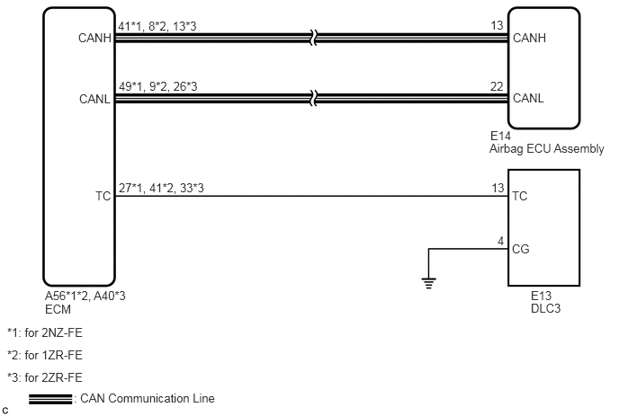
C265835E42
1.375,0.917 2.448,1.167 1.073,0.25 10 false 49*1, 9*2, 26*3 1.365,0.219 2.677,0.521 1.313,0.302 10 false 41*1, 8*2, 13*3 1.375,2.094 2.542,2.51 1.167,0.417 10 false 27*1, 41*2, 33*3 0.917,1.063 1.396,1.313 0.479,0.25 10 false CANL 0.906,0.354 1.656,0.698 0.75,0.344 10 false CANH 1.104,2.188 1.531,2.604 0.427,0.417 10 false TC 0.521,3.344 2.24,3.542 1.719,0.198 10 false A56*1*2, A40*3 0.521,3.5 1,3.823 0.479,0.323 10 false ECM 0.083,3.771 4.406,3.969 4.323,0.198 10 false *1: for 2NZ-FE 5.927,2.188 6.26,2.542 0.333,0.354 10 false TC 5.688,2.094 6.042,2.427 0.354,0.333 10 false 13 5.76,2.708 5.979,3.042 0.219,0.333 10 false 4 5.927,2.802 6.25,3.104 0.323,0.302 10 false CG 6.146,3.344 6.573,3.573 0.427,0.229 10 false E13 6.146,3.49 6.646,3.833 0.5,0.344 10 false DLC3 5.938,1.052 6.448,1.417 0.51,0.365 10 false CANL 5.677,1.49 6.021,1.74 0.344,0.25 10 false E14 5.677,0.917 6,1.281 0.323,0.365 10 false 22 5.677,0.208 5.948,0.521 0.271,0.313 10 false 13 5.938,0.354 6.406,0.698 0.469,0.344 10 false CANH 5.667,1.635 7.115,2.063 1.448,0.427 10 false Airbag ECU Assembly 0.854,4.531 2.615,4.75 1.76,0.219 10 false : CAN Communication Line 0.083,4.292 2.823,4.563 2.74,0.271 10 false *3: for 2ZR-FE 0.083,4.031 4.417,4.281 4.333,0.25 10 false *2: for 1ZR-FE

PROCEDURE

1.CHECK WIRE HARNESS (TC OF DLC3 - TC OF ECM)
a.

Turn the ignition switch off.

C295789C09
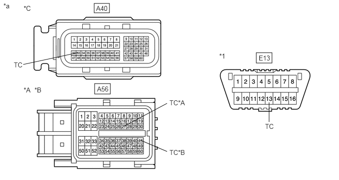
1.99,0.073 2.313,0.271 0.323,0.198 2,1.771 2.333,1.99 0.333,0.219 5.417,1.115 5.75,1.333 0.333,0.219 2.969,2.969 3.531,3.208 false 5.688,2.167 5.688,2.583 false 0.49,1.365 1.646,1.115 false 2.615,2.677 3.531,2.188 false 0.5,0.094 0.875,0.417 0.375,0.323 10 false *C 0.5,1.823 0.917,2.406 0.417,0.583 10 false *A 4.635,1.104 4.969,1.417 0.333,0.313 10 false *1 0.073,0.042 0.448,0.323 0.375,0.281 10 false *a 2.031,0.094 2.448,0.677 0.417,0.583 10 false A40 0.292,1.292 0.708,1.875 0.417,0.583 10 false TC 2.052,1.802 2.469,2.385 0.417,0.583 10 false A56 3.583,3.146 4.167,3.573 0.583,0.427 10 false TC*B 5.469,1.146 5.885,1.729 0.417,0.583 10 false E13 5.604,2.594 6.021,3.177 0.417,0.583 10 false TC 0.729,1.823 1.146,2.406 0.417,0.583 10 false *B 3.583,2.094 4.167,2.521 0.583,0.427 10 false TC*A
*A for 2NZ-FE *B for 1ZR-FE
*C for 2ZR-FE - -
*1 DLC3 - -
*a Front view of wire harness connector
(to ECM)
- -


b.

Disconnect the connector from the ECM.


c.

Measure the resistance according to the value(s) in the table below.

Standard Resistance:
for 2NZ-FE:
Tester Connection Condition Specified Condition
E13-13 (TC) - A56-27 (TC) Always Below 1 Ω

for 1ZR-FE:
Tester Connection Condition Specified Condition
E13-13 (TC) - A56-41 (TC) Always Below 1 Ω

for 2ZR-FE:
Tester Connection Condition Specified Condition
E13-13 (TC) - A40-33 (TC) Always Below 1 Ω


Result:
Proceed to
OK
NG


OK

2.CHECK WIRE HARNESS (CG OF DLC3 - BODY GROUND)

NG

REPAIR OR REPLACE WIRE HARNESS

2.CHECK WIRE HARNESS (CG OF DLC3 - BODY GROUND)
a.
C204945C31
0.135,0.979 0.469,1.198 0.333,0.219 1.615,0.802 1.615,0.302 1.615,0.302 1.813,0.302 false 0.156,0.135 0.469,0.396 0.313,0.26 10 false *1 0.188,1.01 0.5,1.313 0.313,0.302 10 false E13 1.854,0.219 2.25,0.469 0.396,0.25 10 false CG
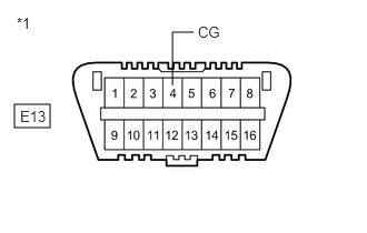
*1 DLC3


Measure the resistance according to the value(s) in the table below.

Standard Resistance:
Tester Connection Condition Specified Condition
E13-4 (CG) - Body ground Always Below 1 Ω


Result:
Proceed to
OK
NG


OK

3.CHECK WIRE HARNESS (TC OF DLC3 - BODY GROUND)

NG

REPAIR OR REPLACE WIRE HARNESS

3.CHECK WIRE HARNESS (TC OF DLC3 - BODY GROUND)
a.
C204945C32
0.188,0.958 0.521,1.188 0.333,0.229 1.958,1.76 1.792,1.76 1.792,1.76 1.792,1.344 false 0.125,0.115 0.406,0.396 0.281,0.281 10 false *1 0.25,0.99 0.813,1.448 0.563,0.458 10 false E13 2.021,1.688 2.354,1.979 0.333,0.292 10 false TC
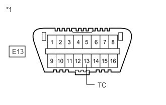
*1 DLC3


Measure the resistance according to the value(s) in the table below.

Standard Resistance:
Tester Connection Condition Specified Condition
E13-13 (TC) - Body ground Always 1 MΩ or higher


Result:
Proceed to
OK
NG


OK

NG

REPAIR OR REPLACE WIRE HARNESS OR REPLACE EACH ECU