THEFT DETERRENT / KEYLESS ENTRY IMMOBILISER SYSTEM(w/o Smart Entry and Start System) B2780 Push Switch / Key Unlock Warning Switch Malfunction
DESCRIPTION
This DTC is stored if the transponder key ECU assembly does not detect that the unlock warning switch assembly is on even when the ignition switch is ON.
| DTC No. | Detection Item | DTC Detection Condition | Trouble Area | Note |
|---|---|---|---|---|
| B2780 | Push Switch / Key Unlock Warning Switch Malfunction | The unlock warning switch assembly is not detected as being on when the ignition switch is ON (1 trip detection logic*). | ·
Wire harness or connector ·
Unlock warning switch assembly ·
Transponder key ECU assembly |
DTC Output Confirmation Operation:
Insert the door control transmitter assembly into the ignition key cylinder. |
*: Only output while a malfunction is present.
| Vehicle Condition when Malfunction Detected | Fail-safe Operation when Malfunction Detected |
|---|---|
| Engine cannot be started | - |
| DTC No. | Data List and Active Test |
|---|---|
| B2780 | Key SW |
WIRING DIAGRAM
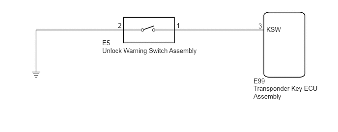
CAUTION / NOTICE / HINT
- NOTICE:
- ·
If the transponder key ECU assembly is replaced, refer to Service Bulletin.
·After repair, confirm that no DTCs are output by performing "DTC Output Confirmation Operation".
PROCEDURE
Clear the DTCs.
- Body Electrical > Immobiliser > Clear DTCs
- 50002 260
- Result:
Proceed to NEXT
NEXT
Perform "DTC Output Confirmation Operation" procedure.
Check for DTCs.
- Body Electrical > Immobiliser > Trouble Codes
- 50001 260
- OK:
DTC B2780 is not output.
- Result:
Result Proceed to B2780 is not output A B2780 is output B
A
Click hereGeneral>INTRODUCTION>HOW TO TROUBLESHOOT ECU CONTROLLED SYSTEMS>HOW TO PROCEED WITH TROUBLESHOOTING
B
Remove the unlock warning switch assembly.
Click hereVehicle Interior>DOOR LOCK>UNLOCK WARNING SWITCH>REMOVAL
Inspect the unlock warning switch assembly.
Click hereVehicle Interior>DOOR LOCK>UNLOCK WARNING SWITCH>INSPECTION
- Result:
Proceed to OK NG
OK
NG
Disconnect the E99 transponder key ECU assembly connector.
Measure the resistance according to the value(s) in the table below.
- Standard Resistance:
Tester Connection Condition Specified Condition E5-1 - E99-3 (KSW) Always Below 1 Ω E5-2 - Body ground Always Below 1 Ω E5-1 or E99-3 (KSW) - Body ground Always 10 kΩ or higher
- Result:
Proceed to OK NG
OK
NG