U441E AUTOMATIC TRANSMISSION / TRANSAXLE VALVE BODY ASSEMBLY INSTALLATION
PROCEDURE

 35148
1.INSTALL NO. 1 GOVERNOR APPLY GASKET
35148
1.INSTALL NO. 1 GOVERNOR APPLY GASKET
Apply a light coat of ATF to a new No. 1 governor apply gasket and install it to the automatic transaxle case sub-assembly.
35251
2.INSTALL CHECK BALL BODY
Install the check ball body compression spring and check ball body to the automatic transaxle case sub-assembly.
35410
3.INSTALL TRANSMISSION VALVE BODY ASSEMBLY
Connect the manual valve connecting rod to the manual valve lever sub-assembly.
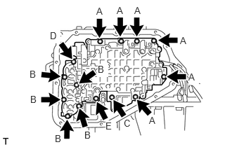
Temporarily install the transmission valve body assembly to the automatic transaxle case sub-assembly with the 14 bolts.
- HINT:
-
Bolt length:
- ·
Bolt (A): 20 mm (0.787 in.)
·Bolt (B): 28 mm (1.10 in.)
·Bolt (C): 36 mm (1.42 in.)
·Bolt (D): 40 mm (1.57 in.)
·Bolt (E): 49 mm (1.93 in.)
Tighten the 14 bolts.
- Torque:
- 10.8 N*m (110 kgf*cm, 8 ft.*lbf)
82125J
4.CONNECT TRANSMISSION WIRE
Connect the shift solenoid valve ST connector.
Connect the shift solenoid valve SL connector.
Connect the shift solenoid valve SLT connector.
Connect the shift solenoid valve S2 connector.
Connect the shift solenoid valve S1 connector.
Engage the 2 clamps.
Engage the temperature sensor clamp.
35330
5.INSTALL VALVE BODY OIL STRAINER ASSEMBLY
Install the valve body oil strainer assembly to the transmission valve body assembly with the 3 bolts.
- Torque:
- 9.8 N*m (100 kgf*cm, 87 in.*lbf)
35394
6.INSTALL TRANSMISSION OIL CLEANER MAGNET
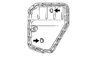
Install the 2 transmission oil cleaner magnets to the automatic transaxle oil pan sub-assembly as shown in the illustration.
35106D
7.INSTALL AUTOMATIC TRANSAXLE OIL PAN SUB-ASSEMBLY
Install a new automatic transaxle oil pan gasket and automatic transaxle oil pan sub-assembly to the automatic transaxle case sub-assembly with the 18 bolts.
- Torque:
- 7.0 N*m (71 kgf*cm, 62 in.*lbf)
- NOTICE:
-
Completely remove any oil or grease from the contact surface of the automatic transaxle case sub-assembly and automatic transaxle oil pan sub-assembly with the automatic transaxle oil pan gasket before installation.
8.ADD AUTOMATIC TRANSAXLE FLUID
Pull out the transmission oil level dipstick sub-assembly from the transmission oil filler tube sub-assembly.
Add ATF to the automatic transaxle assembly through the transmission oil filler tube sub-assembly.
- Automatic Transaxle Fluid (ATF):
Classification Capacity
(Reference)ATF Dry fill 5.6 liters (5.9 US qts, 4.9 Imp. qts) Drain and refill 2.0 liters (2.1 US qts, 1.8 Imp. qts)
9.INSPECT AUTOMATIC TRANSAXLE FLUID
10.INSPECT FOR AUTOMATIC TRANSAXLE FLUID LEAK
51442C
11.INSTALL ENGINE UNDER COVER LH