1ZR-FE ENGINE MECHANICAL CYLINDER HEAD INSPECTION
PROCEDURE

 11101
1.INSPECT CYLINDER HEAD SUB-ASSEMBLY FOR FLATNESS
11101
1.INSPECT CYLINDER HEAD SUB-ASSEMBLY FOR FLATNESS
Using a precision straightedge and feeler gauge, check the surfaces which contact the cylinder block sub-assembly and manifolds for warpage.
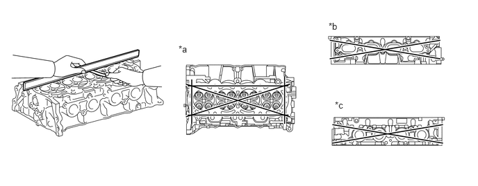
| *a | Cylinder Block Sub-assembly Side | *b | Intake Manifold Side |
| *c | Exhaust Manifold Side | - | - |
- Maximum Warpage:
Item Specified Condition Cylinder block sub-assembly side 0.05 mm (0.00197 in.) Intake manifold side 0.10 mm (0.00394 in.) Exhaust manifold side 0.10 mm (0.00394 in.)
If the warpage is greater than the maximum, replace the cylinder head sub-assembly.
11101
2.INSPECT CYLINDER HEAD SUB-ASSEMBLY FOR CRACKS
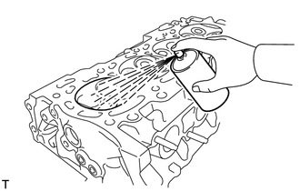
Using a dye penetrant, check the intake ports, exhaust ports and cylinder head surface for cracks.
If cracked, replace the cylinder head sub-assembly.
3.INSPECT VALVE SEATS
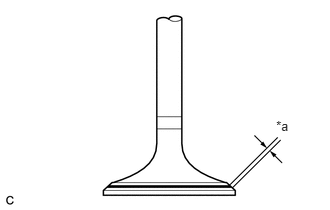
| *a | Width |
Apply a light coat of Prussian blue to the valve face.
Lightly press the valve face against the valve seat.
- HINT:
-
Do not rotate the valve while pressing the valve.
Check the valve face and valve seat.
Intake Side:
Check that the contact surfaces of the valve seat and valve face are in the middle area of their respective surfaces, with the width between 1.0 and 1.4 mm (0.0394 and 0.0551 in.).
If not, resurface the valve seat.
Exhaust Side:
Check that the contact surfaces of the valve seat and valve face are in the middle area of their respective surfaces, with the width between 1.0 and 1.4 mm (0.0394 and 0.0551 in.).
If not, resurface the valve seat.
Check that the contact surfaces of the valve seat and valve face are even around the entire valve seat.
If not, resurface the valve seat.
4.INSPECT CAMSHAFT THRUST CLEARANCE
Install the camshafts.
Click hereEngine / Hybrid System>1ZR-FE ENGINE MECHANICAL>CAMSHAFT>INSTALLATION
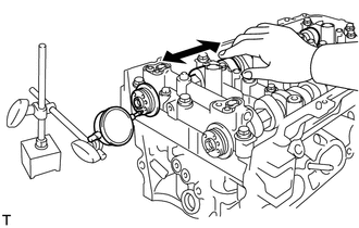
Using a dial indicator, measure the thrust clearance while moving the camshaft back and forth.
- Standard Thrust Clearance:
Item Specified Condition Intake 0.06 to 0.155 mm (0.00236 to 0.00610 in.) Exhaust 0.06 to 0.155 mm (0.00236 to 0.00610 in.)
- Maximum Thrust Clearance:
Item Specified Condition Intake 0.17 mm (0.00669 in.) Exhaust 0.17 mm (0.00669 in.)
If the thrust clearance is greater than the maximum, replace the camshaft housing sub-assembly. If the thrust surface is damaged, replace the camshaft.
5.INSPECT CAMSHAFT OIL CLEARANCE
Clean the camshaft bearing caps and camshaft journals.
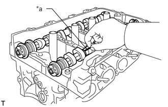
Place the camshafts on the camshaft housing sub-assembly.
| *a | Plastigage |
Lay a strip of Plastigage across each camshaft journal.
Install the camshaft bearing caps.
Click hereEngine / Hybrid System>1ZR-FE ENGINE MECHANICAL>CAMSHAFT>INSTALLATION
- NOTICE:
-
Do not turn the camshaft.
Remove the camshaft bearing caps.
Click hereEngine / Hybrid System>1ZR-FE ENGINE MECHANICAL>CAMSHAFT>REMOVAL
| *a | Plastigage |
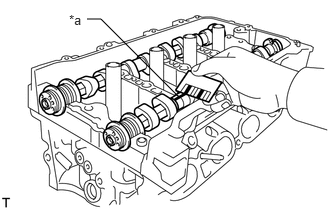
Measure the Plastigage at its widest point.
- Standard Oil Clearance:
Item Specified Condition Camshaft No. 1 journal 0.030 to 0.063 mm (0.00118 to 0.00248 in.) Camshaft other journals 0.035 to 0.072 mm (0.00138 to 0.00283 in.)
- Maximum Oil Clearance:
Item Specified Condition Camshaft No. 1 journal 0.085 mm (0.00335 in.) Camshaft other journals 0.09 mm (0.00354 in.)
- NOTICE:
-
Completely remove the Plastigage after the inspection.
If the oil clearance is greater than the maximum, replace the camshaft. If necessary, replace the camshaft housing sub-assembly.
13711B
6.INSPECT INNER COMPRESSION SPRING
- HINT:
-
 0.229,0.052 1.563,3.208 1.333,3.156 1.802,0.052 3.135,3.208 1.333,3.156 0.438,0.615 0.531,0.479 false 2.042,0.625 2.135,0.49 false 0.448,0.969 0.667,0.969 false 2.094,0.969 2.313,0.969 false 0.458,1.615 0.677,1.615 false 2.073,1.667 2.292,1.667 false 0.563,2.719 0.781,2.719 false 2.167,2.729 2.385,2.729 false 0.26,0.094 0.573,0.25 0.313,0.156 10 false *A 1.833,0.115 2.146,0.271 0.313,0.156 10 false *B 0.271,0.604 0.583,0.76 0.313,0.156 10 false *1 0.281,0.917 0.594,1.073 0.313,0.156 10 false *2 0.292,1.563 0.604,1.719 0.313,0.156 10 false *3 0.385,2.667 0.698,2.823 0.313,0.156 10 false *4 1.885,0.625 2.198,0.781 0.313,0.156 10 false *1 1.917,0.917 2.229,1.073 0.313,0.156 10 false *2 1.906,1.615 2.219,1.771 0.313,0.156 10 false *3 1.99,2.667 2.302,2.823 0.313,0.156 10 false *4
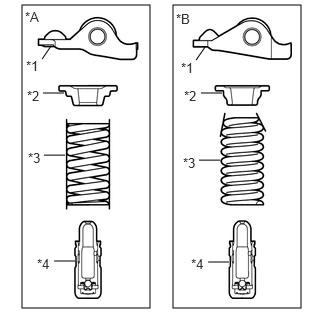
*A Type A *B Type B *1 No. 1 Valve Rocker Arm Sub-assembly *2 Valve Spring Retainer *3 Compression Spring *4 Valve Lash Adjuster Assembly
-
Type A and Type B can be distinguished by the shape of the compression spring.
Type Compression Spring Shape A Straight B Tapered
Type A:
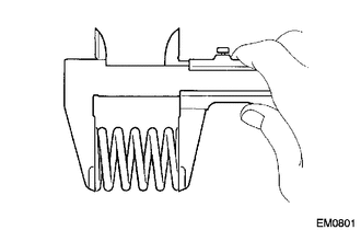
Using a vernier caliper, measure the free length of the inner compression spring.
- Standard free length:
53.88 mm (2.12 in.)
If the free length is not as specified, replace the inner compression spring.
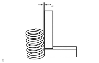
| *a | Deviation |
Using a steel square, measure the deviation of the inner compression spring.
- Maximum deviation:
1.0 mm (0.0394 in.)
If the deviation is more than the maximum, replace the inner compression spring.
Type B:
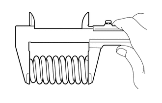
Using a vernier caliper, measure the free length of the inner compression spring.
- Standard free length:
51.88 mm (2.042 in.) or 51.90 mm (2.043 in.)
If the free length is not as specified, replace the inner compression spring.
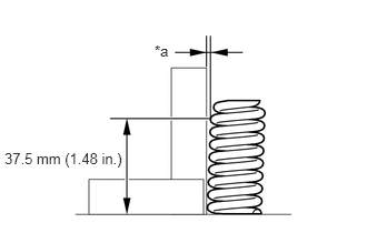
| *a | Deviation |
Using a steel square, measure the deviation of the inner compression spring.
- Maximum deviation:
1.3 mm (0.0512 in.)
If the deviation is more than the maximum, replace the inner compression spring.
13711
7.INSPECT INTAKE VALVE
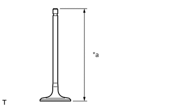
| *a | Overall Length |
Using a vernier caliper, measure the overall length of the intake valve.
- Standard Overall Length:
109.34 mm (4.30 in.)
- Minimum Overall Length:
108.84 mm (4.29 in.)
If the overall length is less than the minimum, replace the intake valve.
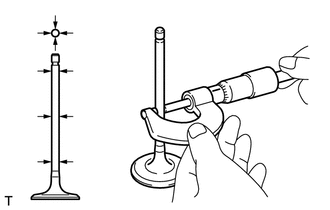
Using a micrometer, measure the diameter of the intake valve stem.
- Standard Valve Stem Diameter:
5.470 to 5.485 mm (0.2154 to 0.2159 in.)
If the intake valve stem diameter is not as specified, check the intake valve guide bush oil clearance.
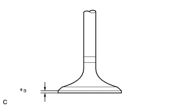
| *a | Margin Thickness |
Using a vernier caliper, measure the intake valve head margin thickness.
- Standard Margin Thickness:
1.0 mm (0.0394 in.)
- Minimum Margin Thickness:
0.5 mm (0.0197 in.)
If the margin thickness is less than the minimum, replace the intake valve.
13715
8.INSPECT EXHAUST VALVE
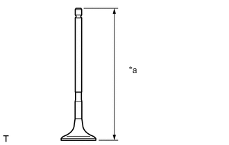
| *a | Overall Length |
Using a vernier caliper, measure the overall length of the exhaust valve.
- Standard Overall Length:
108.25 mm (4.26 in.)
- Minimum Overall Length:
107.75 mm (4.24 in.)
If the overall length is less than the minimum, replace the exhaust valve.
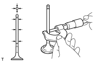
Using a micrometer, measure the diameter of the exhaust valve stem.
- Standard Valve Stem Diameter:
5.465 to 5.480 mm (0.2152 to 0.2157 in.)
If the exhaust valve stem diameter is not as specified, check the exhaust valve guide bush oil clearance.
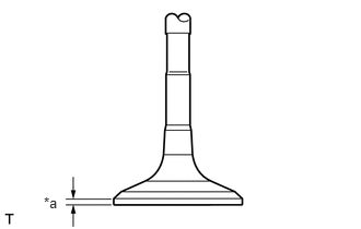
| *a | Margin Thickness |
Using a vernier caliper, measure the exhaust valve head margin thickness.
- Standard Margin Thickness:
1.01 mm (0.0398 in.)
- Minimum Margin Thickness:
0.5 mm (0.0197 in.)
If the margin thickness is less than the minimum, replace the exhaust valve.
9.INSPECT VALVE GUIDE BUSH OIL CLEARANCE
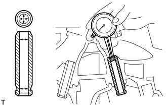
Using a caliper gauge, measure the inside diameter of the valve guide bush.
- Standard Valve Guide Bush Inside Diameter:
5.510 to 5.530 mm (0.2169 to 0.2177 in.)
Subtract the valve stem diameter measurement from the valve guide bush inside diameter measurement.
- Standard Oil Clearance:
Item Specified Condition Intake 0.025 to 0.060 mm (0.000984 to 0.00236 in.) Exhaust 0.030 to 0.065 mm (0.00118 to 0.00256 in.)
- Maximum Oil Clearance:
Item Specified Condition Intake 0.080 mm (0.00315 in.) Exhaust 0.085 mm (0.00335 in.)
If the oil clearance is greater than the maximum, replace the valve and valve guide bush.