THEFT DETERRENT / KEYLESS ENTRY IMMOBILISER SYSTEM(w/o Smart Entry and Start System) B2799 Engine Immobiliser System Malfunction
DESCRIPTION
The ECM stores this DTC when a communication line between the ECM and transponder key ECU assembly is malfunctioning or the communication ID of the ECM and transponder key ECU assembly do not match.
| DTC No. | Detection Item | DTC Detection Condition | Trouble Area | Note |
|---|---|---|---|---|
| B2799 | Engine Immobiliser System Malfunction | One of the following conditions is met:
·
Error in communication between ECM and transponder key ECU assembly. ·
Error in communication lines. ·
Communication ID is different during communication between ECM and transponder key ECU assembly. |
·
Wire harness or connector ·
Transponder key ECU assembly ·
ECM |
DTC Output Confirmation Operation:
·
Start the engine and wait 10 seconds. ·
After disconnecting and reconnecting the cable to the negative (-) battery terminal, turn the ignition switch to ON and wait 10 seconds. |
| Vehicle Condition when Malfunction Detected | Fail-safe Operation when Malfunction Detected |
|---|---|
| Engine cannot be started | - |
| DTC No. | Data List and Active Test |
|---|---|
| B2799 | - |
WIRING DIAGRAM
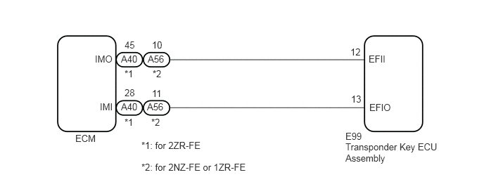
CAUTION / NOTICE / HINT
- NOTICE:
- ·
If the transponder key ECU assembly or ECM is replaced, refer to Service Bulletin.
·After repair, confirm that no DTCs are output by performing "DTC Output Confirmation Operation".
- HINT:
-
If transponder key ECU assembly DTCs are output simultaneously, troubleshoot the transponder key ECU assembly DTCs first.
PROCEDURE
Clear the DTCs.
- Powertrain > Engine and ECT > Clear DTCs
- 50002 234
- Result:
Proceed to NEXT
NEXT
Perform "DTC Output Confirmation Operation" procedure.
Check for DTCs.
- Powertrain > Engine and ECT > Trouble Codes
- 50001 234
- OK:
B2799 is not output.
- Result:
Result Proceed to OK A NG (DTC B2799 is output) B NG (Other DTCs are output) C
A
Click hereGeneral>INTRODUCTION>HOW TO TROUBLESHOOT ECU CONTROLLED SYSTEMS>HOW TO PROCEED WITH TROUBLESHOOTING
B
C
for 2ZR-FE
Using an oscilloscope, check the waveform.
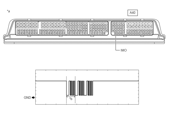
| *a | Component with harness connected
(ECM) |
*b | Waveform |
| Tester Connection | Condition | Tool Setting | Specified Condition |
|---|---|---|---|
| A40-45 (IMO) - Body ground | Within 3 seconds of starter operation and initial combustion, or within 3 seconds of ignition switch first being turned to ON after cable disconnected and reconnected to negative (-) battery terminal | 2 V/DIV., 500 ms./DIV. | Pulse generation
(See waveform) |
for 2NZ-FE or 1ZR-FE
Using an oscilloscope, check the waveform.
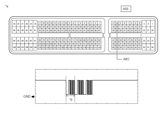
| *a | Component with harness connected
(ECM) |
*b | Waveform |
| Tester Connection | Condition | Tool Setting | Specified Condition |
|---|---|---|---|
| A56-10 (IMO) - Body ground | Within 3 seconds of starter operation and initial combustion, or within 3 seconds of ignition switch first being turned to ON after cable disconnected and reconnected to negative (-) battery terminal | 2 V/DIV., 500 ms./DIV. | Pulse generation
(See waveform) |
- OK:
Waveform is similar to that shown in the illustration.
- Result:
Result Proceed to OK A NG (Terminal IMO stuck low (2.4 V or less)) B NG (Terminal IMO stuck high (12 V) or abnormal waveform) C
A
B
C
for 2ZR-FE
Using an oscilloscope, check the waveform.
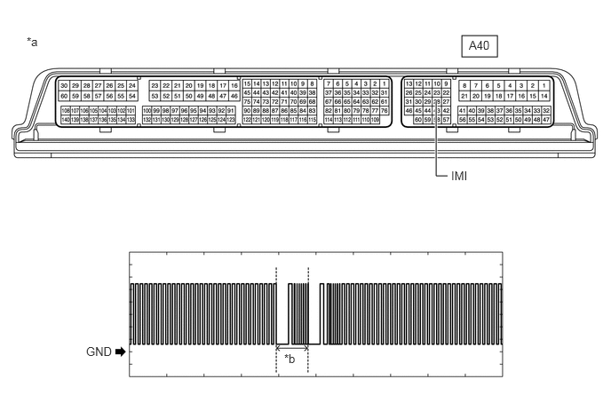
| *a | Component with harness connected
(ECM) |
*b | Waveform |
| Tester Connection | Condition | Tool Setting | Specified Condition |
|---|---|---|---|
| A40-28 (IMI) - Body ground | Ignition switch ON | 2 V/DIV., 500 ms./DIV. | Pulse generation
(See waveform) |
for 2NZ-FE or 1ZR-FE
Using an oscilloscope, check the waveform.
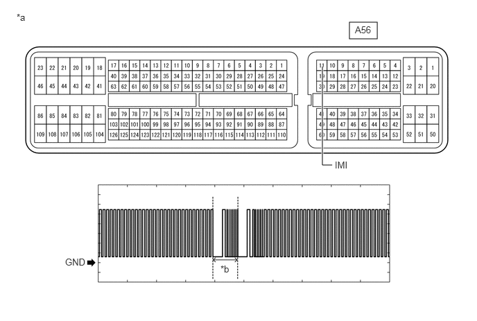
| *a | Component with harness connected
(ECM) |
*b | Waveform |
| Tester Connection | Condition | Tool Setting | Specified Condition |
|---|---|---|---|
| A56-11 (IMI) - Body ground | Ignition switch ON | 2 V/DIV., 500 ms./DIV. | Pulse generation
(See waveform) |
- Result:
Proceed to OK NG
OK
NG
Register the ECU communication ID.
- HINT:
-
Refer to Service Bulletin.
- Result:
Proceed to NEXT
NEXT
Using a registered door control transmitter assembly, turn the ignition switch to ON.
Check that the engine starts 5 seconds after the ignition switch was turned to ON.
- OK:
Engine starts normally.
- Result:
Proceed to OK NG
OK
NG
for 2ZR-FE
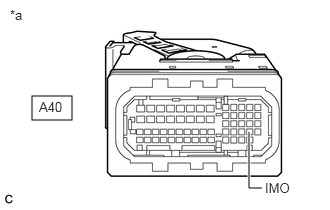
| *a | Front view of wire harness connector
(to ECM) |
Disconnect the A40 ECM connector.
Turn the ignition switch to ON.
Measure the voltage according to the value(s) in the table below.
- Standard Voltage:
Tester Connection Condition Result A40-45 (IMO) - Body ground Ignition switch turned to ON using registered door control transmitter assembly Terminal IMO stuck low (2.4 V or less) Terminal IMO stuck high (12 V) or abnormal waveform
for 2NZ-FE or 1ZR-FE
Disconnect the A56 ECM connector.
Turn the ignition switch to ON.
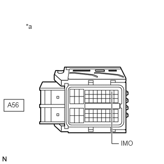
| *a | Front view of wire harness connector
(to ECM) |
Measure the voltage according to the value(s) in the table below.
- Standard Voltage:
Tester Connection Condition Result A56-10 (IMO) - Body ground Ignition switch turned to ON using registered key Terminal IMO stuck low (2.4 V or less) Terminal IMO stuck high (12 V) or abnormal waveform
- Result:
Result Proceed to Terminal IMO stuck low (2.4 V or less) A Terminal IMO stuck high (12 V) or abnormal waveform B
A
B
for 2ZR-FE
Disconnect the E99 transponder key ECU assembly connector.
Measure the resistance according to the value(s) in the table below.
- Standard Resistance:
Tester Connection Condition Specified Condition E99-12 (EFII) - A40-45 (IMO) Always Below 1 Ω E99-12 (EFII) or A40-45 (IMO) - Body ground Always 10 kΩ or higher
for 2NZ-FE or 1ZR-FE
Disconnect the E99 transponder key ECU assembly connector.
Measure the resistance according to the value(s) in the table below.
- Standard Resistance:
Tester Connection Condition Specified Condition E99-12 (EFII) - A56-10 (IMO) Always Below 1 Ω E99-12 (EFII) or A56-10 (IMO) - Body ground Always 10 kΩ or higher
- Result:
Proceed to OK NG
OK
NG
Replace the transponder key ECU assembly with a new one.
- HINT:
-
Refer to Service Bulletin.
- NOTICE:
-
Key ID code registration is necessary when replacing the transponder key ECU assembly, refer to Service Bulletin.
- Result:
Proceed to NEXT
NEXT
Using a registered door control transmitter assembly, turn the ignition switch to ON.
Check that the engine starts 5 seconds after the ignition switch was turned to ON.
- OK:
Engine starts normally.
- Result:
Proceed to OK NG
OK
NG
for 2ZR-FE: Click hereEngine / Hybrid System>2ZR-FE ENGINE CONTROL>ECM>REMOVAL
for 1ZR-FE: Click hereEngine / Hybrid System>1ZR-FE ENGINE CONTROL>ECM>REMOVAL
for 2NZ-FE: Click hereEngine / Hybrid System>2NZ-FE ENGINE CONTROL>ECM>REMOVAL
Temporarily replace the ECM with a new one.
for 2ZR-FE: Click hereEngine / Hybrid System>2ZR-FE ENGINE CONTROL>ECM>REMOVAL
for 1ZR-FE: Click hereEngine / Hybrid System>1ZR-FE ENGINE CONTROL>ECM>REMOVAL
for 2NZ-FE: Click hereEngine / Hybrid System>2NZ-FE ENGINE CONTROL>ECM>REMOVAL
- Result:
Proceed to NEXT
NEXT
Register the ECU communication ID.
- HINT:
-
Refer to Service Bulletin.
- Result:
Proceed to NEXT
NEXT
Using a registered door control transmitter assembly, turn the ignition switch to ON.
Check that the engine starts 5 seconds after the ignition switch was turned to ON.
- OK:
Engine starts normally.
- Result:
Proceed to OK NG
OK
NG