THEFT DETERRENT / KEYLESS ENTRY IMMOBILISER SYSTEM(w/ Smart Entry and Start System) Security Indicator Light Does not Blink
DESCRIPTION
The certification ECU (smart key ECU assembly) blinks the security indicator light when the immobiliser is set (engine switch off, or driver door opened and closed with engine switch on (IG)).
WIRING DIAGRAM
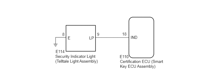
CAUTION / NOTICE / HINT
- NOTICE:
- ·
When using the GTS with the engine switch off, connect the GTS to the DLC3 and turn a courtesy light switch on and off at intervals of 1.5 seconds or less until communication between the GTS and the vehicle begins. Then select Model Code "KEY REGIST" under manual mode and enter the following menus: Body Electrical / Entry&Start(CAN). While using the GTS, periodically turn a courtesy light switch on and off at intervals of 1.5 seconds or less to maintain communication between the GTS and the vehicle.
·Before replacing the certification ECU (smart key ECU assembly), refer to Service Bulletin.
·The immobiliser system uses the CAN communication system. Inspect the communication function by following How to Proceed with Troubleshooting. Troubleshoot the immobiliser system after confirming that the communication systems are functioning properly.
PROCEDURE
Connect the GTS to the DLC3.
Turn the engine switch on (IG).
Turn the GTS on.
Enter the following menus: Body Electrical / Entry&Start / Active Test.
Perform the Active Test according to the display on the GTS.
- Body Electrical > Entry&Start > Active Test
-
Tester Display Measurement Item Control Range Diagnostic Note Immobiliser Indicator Security indicator light OFF/ON -
- Body Electrical > Entry&Start > Active Test
-
Tester Display Immobiliser Indicator - 50004 125 28
- OK:
The security indicator light operates normally.
- Result:
Proceed to OK NG
OK
NG
Remove the security indicator light (telltale light assembly).
Click hereVehicle Interior>THEFT DETERRENT / KEYLESS ENTRY>SECURITY INDICATOR LIGHT ASSEMBLY>REMOVAL
Inspect the security indicator light (telltale light assembly).
Click hereVehicle Interior>THEFT DETERRENT / KEYLESS ENTRY>SECURITY INDICATOR LIGHT ASSEMBLY>INSPECTION
- Result:
Proceed to OK NG
OK
NG
Click hereVehicle Interior>THEFT DETERRENT / KEYLESS ENTRY>SECURITY INDICATOR LIGHT ASSEMBLY>REMOVAL
Disconnect the E110 certification ECU (smart key ECU assembly) connector.
Disconnect the E114 security indicator light (telltale light assembly) connector.
Measure the resistance according to the value(s) in the table below.
- Standard Resistance:
Tester Connection Condition Specified Condition E114-9 (LP) - E110-18 (IND) Always Below 1 Ω E114-9 (LP) - Body ground Always 10 kΩ or higher E110-18 (IND) - Body ground Always 10 kΩ or higher
- Result:
Proceed to OK NG
OK
NG
Measure the resistance according to the value(s) in the table below.
- Standard Resistance:
Tester Connection Condition Specified Condition E114-8 (E) - Body ground Always Below 1 Ω
- Result:
Proceed to OK NG
OK
NG