THEFT DETERRENT / KEYLESS ENTRY SMART ENTRY AND START SYSTEM(for Start Function) DATA LIST / ACTIVE TEST
DATA LIST
- HINT:
-
Using the GTS to read the Data List allows the values or states of switches, sensors, actuators and other items to be read without removing any parts. This non-intrusive inspection can be very useful because intermittent conditions or signals may be discovered before parts or wiring is disturbed. Reading the Data List information early in troubleshooting is one way to save diagnostic time.
- NOTICE:
-
In the table below, the values listed under "Normal Condition" are reference values. Do not depend solely on these reference values when deciding whether a part is faulty or not.
Connect the GTS to the DLC3.
Turn the engine switch on (IG).
Turn the GTS on.
Enter the following menus: Body Electrical / (desired system) / Data List.
Read the Data List according to the display on the GTS.
- Body Electrical > Power Source Control > Data List
-
Tester Display Measurement Item Range Normal Condition Diagnostic Note Shift P Signal Shift position P* ON or OFF ON: Shift lever in P
OFF: Shift lever not in P·Use this item to determine if the shift position switch is malfunctioning.
·The engine cannot be started when this item is OFF.
Steering Unlock Switch State of steering unlock sensor signal output from steering lock ECU (steering lock actuator assembly) ON or OFF ON: Steering unlocked
OFF: Steering locked·When the shift lever is in P* and the engine switch is off, if any door is opened or closed, the steering is locked.
·When the electrical key transmitter sub-assembly is inside the vehicle and the engine switch is turned on (ACC) or on (IG), the steering unlocks.
·The engine cannot be started when the steering unlock signal is off.
Stop Light Switch1 State of brake pedal* ON or OFF ON: Brake pedal depressed
OFF: Brake pedal released·Use this item to determine whether the stop light switch is malfunctioning.
·The engine cannot be started when this item is OFF.
·When this item is malfunctioning, the engine can be started by pressing and holding the engine switch for a certain period of time.
Start Switch1 Engine switch 1 status ON or OFF ON: Engine switch pressed
OFF: Engine switch not pressed·If the engine switch is pressed for a short time, the display may not change.
·Use this item to determine whether the engine switch input signal is malfunctioning.
Start Switch2 Engine switch 2 status ON or OFF ON: Engine switch pressed
OFF: Engine switch not pressed·Backup for engine switch 1. However, when the engine switch is pressed and held, the control functions only when both engine switch 1 and 2 are normal.
·Behaves the same way as engine switch 1.
Neutral SW/ Clutch SW except Manual Transaxle:Shift position (P and N)
for Manual Transaxle:State of clutch pedal
ON or OFF except Manual Transaxle:ON: Shift lever in P or N
OFF: Shift lever in any position other than P or N
for Manual Transaxle:ON: Clutch pedal depressed
OFF: Clutch pedal released
except Manual Transaxle:·Use this item to determine whether the park/neutral position switch assembly is malfunctioning.
·When the engine cannot be started due to a park/neutral position switch assembly malfunction, OFF is displayed.
for Manual Transaxle:·Use this item to help determine if the clutch start switch assembly is malfunctioning.
·The engine cannot be started when this item is OFF.
Latch Circuit Status of IG related backup circuits ON or OFF ON: Engine switch on (IG)
OFF: Engine switch off·Displays in almost the same manner as the IG1 and IG2 relays.
·When the engine switch is on (ACC), OFF is displayed.
IG1 Relay Monitor(Outside) IG1 relay coil voltage monitor status ON or OFF ON: Engine switch on (IG)
OFF: Engine switch off·Use this item to determine whether the IG1 relay is malfunctioning.
·When the engine switch is on (ACC), OFF is displayed.
IG1 Relay Monitor(Inside) IG1 relay activation ON or OFF ON: Engine switch on (IG)
OFF: Engine switch off·Use this item to determine whether the IG1 relay is malfunctioning.
·When the engine switch is on (ACC), OFF is displayed.
IG2 Relay Monitor(Outside) IG2 relay coil voltage monitor status ON or OFF ON: Engine switch on (IG)
OFF: Engine switch off·Use this item to determine whether the IG2 relay is malfunctioning.
·When the engine switch is on (ACC), OFF is displayed.
IG2 Relay Monitor(Inside) IG2 relay activation ON or OFF ON: Engine switch on (IG)
OFF: Engine switch off·Use this item to determine whether the IG2 relay is malfunctioning.
·When the engine switch is on (ACC), OFF is displayed.
Starter Request Signal Engine start request signal status ON or OFF except Manual Transaxle:ON: With the shift lever in P and brake pedal depressed, the engine switch is pressed and held
OFF: After approx. 1 sec. has elapsed, the engine switch is released
for Manual Transaxle:ON: With the clutch pedal depressed, the engine switch is pressed and held
OFF: After approx. 1 sec. has elapsed, the engine switch is released
·When the engine cannot be started due to a start request signal malfunction, OFF is displayed.
·When the engine switch is pressed, the duration of time that ON is displayed will be extremely short. As such, the engine switch needs to be pressed and held for a certain amount of time.
ACC Relay Monitor ACC relay activation ON or OFF ON: Engine switch on (ACC)
OFF: Engine switch off·When the engine switch is on (IG), ON is displayed.
·While the engine is cranking, OFF is displayed.
Engine Condition Engine state Stop or Run Stop: Engine stopped
Run: Engine running- Vehicle Speed Signal Vehicle being driven or stopped Stop or Run Stop: Vehicle stopped
Run: Vehicle being driven at 5 km/h (3 mph) or more- Power Supply Condition Power supply state All OFF, ACC ON, IG1 ON, IG2 ON or ST ON All OFF: Engine switch off (ACC and IG)
ACC ON: Engine switch on (ACC)
IG1 ON: Engine switch on (IG) (IG1 relay on)
IG2 ON: Engine switch on (IG) (IG2 relay on)
ST ON: Sending engine start request signalSince the IG1 and IG2 relays turn on at approximately the same time, IG1 ON may not be displayed (the IG1 relay turns on for a very short time). Powertrain Type Vehicle identification HV-AT, Cnv-MT, Cnv-AT, Cnv-MMT, S&S-MT, S&S-AT or S&S-MMT Cnv-MT: Conventional M/T (M/T vehicle not equipped with hybrid system)
Cnv-AT: Conventional CVT (CVT vehicle not equipped with hybrid system)
Cnv-MMT: Conventional MMT (MMT vehicle not equipped with hybrid system)
S&S-MT: Stop and start M/T (M/T vehicle not equipped with hybrid system)
S&S-AT: Stop and start CVT (CVT vehicle not equipped with hybrid system)- IG1 Circuit IG1 relay coil circuit malfunction OK or NG OK: Circuit normal
NG: Circuit malfunctioning·Use this item to determine whether the IG1 relay is malfunctioning.
·When the engine cannot be started due to an IG1 relay malfunction, NG is displayed.
IG2 Circuit IG2 relay coil circuit malfunction OK or NG OK: Circuit normal
NG: Circuit malfunctioning·Use this item to determine whether the IG2 relay is malfunctioning.
·When the engine cannot be started due to an IG2 relay malfunction, NG is displayed.
Starter SW Sig Mismatch Engine switch signal 1 and 2 do not match Yes or No Yes: Switch malfunctioning (engine switch signal 1 and 2 do not match)
No: Switch normalThe engine can be started even if the result is Yes. However, emergency engine off while driving by pressing and holding the engine switch and, when the brakes are malfunctioning, emergency engine starting by pressing and holding the engine switch cannot be performed. Park Signal Mismatch P position signal malfunction* Yes or No Yes: Signal malfunction (CAN communication and direct line signal do not match)
No: Signal normalEven when Yes is displayed, it is still possible to turn the engine switch off (the power source mode will not be stuck in on (ACC) or on (IG)). Str Lock/Unlock Wait T-Out Steering lock or unlock malfunction Yes or No Yes: Lock or unlock malfunction (e.g. steering lock is stuck etc.)
No: Lock and unlock normalWhen the engine cannot be started due to a steering lock or unlock malfunction, Yes is displayed. Key Certif Wait T-Out Key verification malfunction Yes or No Yes: Verification error (detected due to the electrical key transmitter sub-assembly ID code and the ID code stored in the certification ECU (smart key ECU assembly) not matching)
No: Verification normalWhen the engine cannot be started due to a key verification error, Yes is displayed. Number of Diagnosis Code Number of DTCs 0 to 255 - -
*: except Manual Transaxle
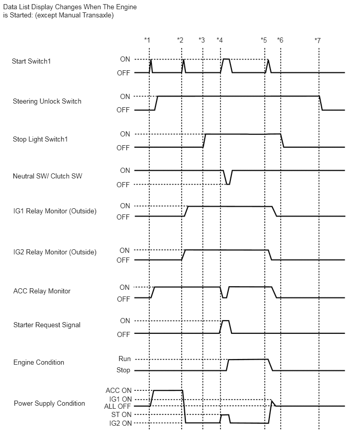
- HINT:
- To check if the Data List display changes, get into the vehicle while carrying an electrical key transmitter sub-assembly and perform the following operations with the engine switch off and the shift lever in P.
-
*1: Press the engine switch with the brake pedal released and check that the engine switch is turned on (ACC).
-
*2: Press the engine switch with the brake pedal released and check that the engine switch is turned on (IG).
-
*3: Depress the brake pedal (stop light switch is on).
-
*4: Press the engine switch with the brake pedal depressed and check that the engine starts.
-
*5: Press the engine switch with the brake pedal depressed and check that the engine switch is turned off.
-
*6: Release the brake pedal.
-
*7: Open a door.
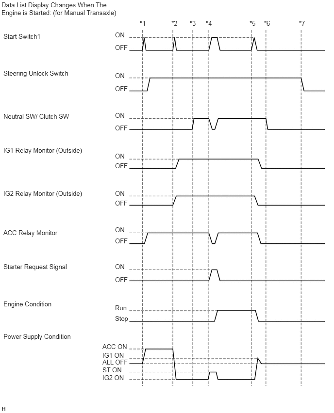
- HINT:
- To check if the Data List display changes, get into the vehicle while carrying an electrical key transmitter sub-assembly and perform the following operations with the engine switch off and the shift lever in neutral.
-
*1: Without depressing the clutch pedal, press the engine switch and check that the power source mode changes to on (ACC).
-
*2: Without depressing the clutch pedal, press the engine switch and check that the power source mode changes to on (IG).
-
*3: Depress the clutch pedal (clutch start switch is on).
-
*4: With the clutch pedal depressed, press the engine switch and check that the engine starts.
-
*5: Press the engine switch and check that the power source mode changes to off.
-
*6: Release the clutch pedal.
-
*7: Open a door.
- Body Electrical > Entry&Start > Data List
-
Tester Display Measurement Item Range Normal Condition Diagnostic Note Ignition Switch Certification ECU (smart key ECU assembly) IG power supply input status ON or OFF ON: Engine switch on (IG)
OFF: Engine switch offWhen the engine switch is on (ACC), OFF is displayed. # Codes Number of DTCs 0 to 255 - - Immobiliser Immobiliser system determined by certification ECU (smart key ECU assembly) Set or Unset Set: Immobiliser set (engine start prohibited) (engine switch off)
Unset: Immobiliser unset (engine start permitted) (engine switch on (ACC) or on (IG))The engine cannot be started when Set is displayed.
- HINT:
- ·
The security indicator light blinks when Set is displayed.
·The security indicator light is linked with set/unset of the immobiliser and not linked with steering lock/unlock.
Auto Entry Cancel SW Smart entry and start system function ON or OFF Customization status displayed - Steering Lock Sleep Cond Steering lock ECU sleep availability Yes or No Yes: Sleep available
No: Sleep not available- Steering Lock Start Cond Steering lock ECU wake up signal status Yes or No Yes: Wake up signal sent
No: Wake up signal not sent- Engine Start Condition Status of engine start permission signal determined by steering lock ECU (steering lock actuator assembly) and sent to certification ECU (smart key ECU assembly) OK or NG OK: Engine start permitted
NG: Engine start prohibited·When OK is displayed, the certification ECU (smart key ECU assembly) receives an unlock confirmation signal from the steering lock ECU (steering lock actuator assembly) and makes fuel injection and engine starting possible.
·The engine cannot be started when NG is displayed.
Sensor Value History of malfunction of position sensor in steering lock ECU (steering lock actuator assembly) (DTC B2781 is stored) OK or NG(Past) OK: History of malfunction for the lock or unlock sensor in the steering lock ECU (steering lock actuator assembly) does not exist.
NG(Past): History of both the lock and unlock sensors in the steering lock ECU (steering lock actuator assembly) being on exists (under normal operation, neither sensor is on).When NG(Past) is displayed, either the position sensor in the steering lock ECU (steering lock actuator assembly) or the assembly itself may be malfunctioning. Power Supply Short History of signal error (short) sent from certification ECU (smart key ECU assembly) to steering lock ECU (steering lock actuator assembly) (DTC B2782 is stored) OK or NG(Past) OK: History of motor power source short does not exist
NG(Past): History of motor power source short existsThis item displays history when a malfunction exists in the circuit between the certification ECU (smart key ECU assembly) and the steering lock ECU (steering lock actuator assembly). Motor Driver Short History of malfunction (short) in the steering lock ECU (steering lock actuator assembly) motor circuit (DTC B2781 is stored). OK or NG(Past) OK: History of short in the motor circuit does not exist
NG(Past): History of short in the motor circuit existsHistory of a malfunction in the steering lock motor circuit in the steering lock ECU (steering lock actuator assembly). Lock/Unlock Receive History of receiving an unlock request signal Yes or No Yes: History of receiving an unlock request signal exists
No: History of receiving an unlock request signal does not exist- Lock Bar Stuck Error History of the steering not being able to unlock properly when the steering lock operates for a certain amount of time OK or NG(Past) OK: History of steering lock being stuck does not exist
NG(Past): History of steering lock being stuck exists- Push Start Error History of push start malfunction due to steering lock ECU (steering lock actuator assembly) OK or NG(Past) OK: History of push start malfunction does not exist
NG(Past): History of push start malfunction exists- Engine Start Request Status of engine start permission signal determined by steering lock ECU (steering lock actuator assembly) and sent to certification ECU (smart key ECU assembly) OK or NG OK: Signal received
NG: Signal not received·When OK is displayed, the certification ECU (smart key ECU assembly) receives an unlock confirmation signal from the steering lock ECU (steering lock actuator assembly) and makes fuel injection and engine starting possible.
·The engine cannot be started when NG is displayed.
S Code Check Verification result between certification ECU (smart key ECU assembly) and ID code box (immobiliser code ECU) OK or NG OK: Verification result normal
NG: Verification result abnormalWhen NG is displayed:
·The ID code for the certification ECU (smart key ECU assembly) or ID code box (immobiliser code ECU) is not registered or the certification ECU (smart key ECU assembly) or ID code box (immobiliser code ECU) is malfunctioning.
·The steering cannot be locked.
·The steering cannot be unlocked (the engine cannot be started).
L Code Check Verification result between ID code box (immobiliser code ECU) and steering lock ECU (steering lock actuator assembly) OK or NG OK: Verification result normal
NG: Verification result abnormalWhen NG is displayed:
·The ID code for the ID code box (immobiliser code ECU) or steering lock ECU (steering lock actuator assembly) is not registered or the ID code box (immobiliser code ECU) or steering lock ECU (steering lock actuator assembly) is malfunctioning.
·The steering cannot be locked.
·The steering cannot be unlocked (the engine cannot be started).
Unlock Request Receive Unlock request signal received state OK or NG OK: Within 10 sec. of turning the engine switch on (IG) or on (ACC), or of an engine start operation being performed
NG: Engine switch on (IG) or on (ACC), or engine start operation not performed·The engine cannot be started when an unlock request signal cannot be received.
·If OK is not displayed even though the steering unlock conditions are met, the certification ECU (smart key ECU assembly) may be malfunctioning.
Lock Request Receive Lock request signal received state
- HINT:
- ·
The reception state is maintained for 10 seconds.
·When 10 seconds or more elapse after receiving the signal, the item changes to "NG".
OK or NG OK: Lock request signal received for 10 sec. of any of the doors being opened with shift lever in P and engine switch off.
NG: Except aboveIf OK is not displayed even though the steering lock conditions are met, the certification ECU (smart key ECU assembly) may be malfunctioning. S Code Check(Past) Verification result history between the certification ECU (smart key ECU assembly) and ID code box (immobiliser code ECU) OK or NG(Past) OK: History of abnormal verification result does not exist
NG(Past): History of abnormal verification result exists- L Code Check(Past) Verification result history between the ID code box (immobiliser code ECU) and steering lock ECU (steering lock actuator assembly) OK or NG(Past) OK: History of abnormal verification result does not exist
NG(Past): History of abnormal verification result exists- Steering Lock Steering lock ECU (steering lock actuator assembly) lock confirmation status Set or Unset Set: Lock confirmed
Unset: Lock not confirmedWhen Unset is displayed, the steering is not locked. Steering Unlock Steering lock ECU (steering lock actuator assembly) unlock confirmation status Set or Unset Set: Unlock confirmed
Unset: Unlock not confirmedWhen Unset is displayed, the steering is not locked (the engine cannot be started). Ignition Available Area Ignition available area Front or All Customization status displayed - Key Low Battery Warning Low transmitter battery warning ON or OFF Customization status displayed - Engine Start Indicator Key warning light ON or OFF Customization status displayed -
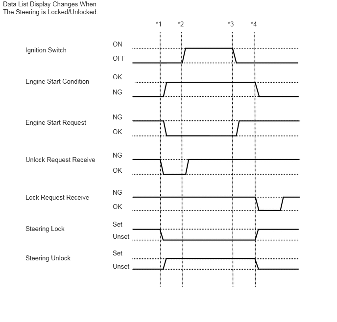
- HINT:
- To check if the Data List display changes, get into the vehicle while carrying an electrical key transmitter sub-assembly and perform the following operations with the engine switch off and the shift lever in P*5.
-
*1: Press the engine switch with the brake pedal*5 or clutch pedal*6 released and check that the engine switch is turned on (ACC).
-
*2: Press the engine switch with the brake pedal*5 or clutch pedal*6 released and check that the engine switch is turned on (IG).
-
*3: Press the engine switch and check that the engine switch is turned off.
-
*4: Release the brake pedal*5 or clutch pedal*6, open the driver door and check that the steering locks.
-
*5: except Manual Transaxle
-
*6: for Manual Transaxle
- Body Electrical > Starting Control > Data List
-
Tester Display Measurement Item Range Normal Condition Diagnostic Note Starter SW Starter operation request ON or OFF ON: Starter operation requested
OFF: Starter operation not requestedWhen malfunctioning, the engine will not crank. Shift Position P or N Park/neutral position switch ON or OFF ON: Shift lever in P or N
OFF: Shift lever not in P or NWhen malfunctioning, the engine will not crank. Starter Relay Starter relay voltage monitor ON or OFF ON: ST relay on
OFF: ST relay offOFF is displayed when the engine cannot crank. Starting Control SW Starter request signal monitor ON or OFF ON: Starting control switch on
OFF: Starting control switch offWhen malfunctioning, the engine cannot crank. Ignition IG2 status ON or OFF ON: IG2 relay on
OFF: IG2 relay off- Engine Speed Engine speed 0 to 16383 r/min Fluctuates in accordance with engine speed - Number of DTCs Number of DTCs 0 to 255 - -
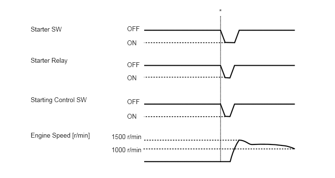
- HINT:
-
*: With the engine switch on (IG), the shift lever in P or N*1 and the brake pedal*1 or clutch pedal*2 depressed, press the engine switch and check that the engine starts.
- ·
*1: except Manual Transaxle
·*2: for Manual Transaxle
- Body Electrical > Combination Meter > Data List
-
Tester Display Measurement Item Range Normal Condition Diagnostic Note Vehicle Speed Meter Vehicle speed 0 to 255 Almost same as actual vehicle speed -
ACTIVE TEST
- HINT:
-
Using the GTS to perform Active Tests allows relays, VSVs, actuators and other items to be operated without removing any parts. This non-intrusive functional inspection can be very useful because intermittent operation may be discovered before parts or wiring is disturbed. Performing Active Tests early in troubleshooting is one way to save diagnostic time. Data List information can be displayed while performing Active Tests.
Connect the GTS to the DLC3.
Turn the engine switch on (IG).
Turn the GTS on.
Enter the following menus: Body Electrical / (desired system) / Active Test.
Perform Active Test according to the display on the GTS.
- Body Electrical > Power Source Control > Active Test
-
Tester Display Measurement Item Control Range Diagnostic Note P Supply for Steering Lock Certification ECU (smart key ECU assembly) OFF/ON
- HINT:
-
OFF: Power is not supplied.
-
ON: Power is supplied.
When performing this Active Test, make sure the following condition is met:
The engine switch is on (IG).
- Body Electrical > Entry&Start > Active Test
-
Tester Display Measurement Item Control Range Diagnostic Note Power/Engine SW Light Engine switch light OFF/ON When performing this Active Test, make sure the following condition is met:
The engine switch illumination is off (15 seconds or more have elapsed since it turned from on to off) and the engine switch is on (ACC) or on (IG), or the engine is running.