THEFT DETERRENT / KEYLESS ENTRY SMART ENTRY AND START SYSTEM(for Start Function) TERMINALS OF ECU
CHECK CERTIFICATION ECU (SMART KEY ECU ASSEMBLY)
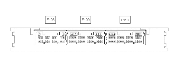
Disconnect the E110 and E108 certification ECU (smart key ECU assembly) connectors.
Measure the voltage and resistance according to the value(s) in the table below.
- HINT:
-
Measure the values on the wire harness side with the connector disconnected.
| Tester Connection | Input/Output | Wiring Color | Terminal Description | Condition | Specified Condition | Related Data List Item |
|---|---|---|---|---|---|---|
| E108-7 (STA) - Body ground | Input | LG - Body ground | When starting the engine, this monitors the voltage sent from terminal STAR to the starter relay to judge whether the engine is "being started". | 20°C (68°F) | 98 to 146 Ω | - |
| E108-5 (STAR) - Body ground*1 | Input/Output | W - Body ground | Outputs voltage to the starter relay
·
Outputs voltage (12 V) to the starter relay when starting the engine. (Max. 30 sec. Turns off when an engine speed of 500 rpm or more continues for 500 ms or more.) |
Shift lever in any position other than P or N → shift lever in P or N (at 20°C (68°F)) | 30 kΩ or higher → 98 to 146 Ω | - |
| Receives park/neutral position switch assembly (P, N position detection) signal
·
Monitors whether the park/neutral position switch assembly is on (P or N) or off (other than P or N). Applies voltage via a resistor (large) in the certification ECU (smart key ECU assembly). When the park/neutral position switch assembly is on, due to the starter relay coil resistance (small) using some of the voltage, the voltage at terminal STAR will be low (2.7 V or less), and when the park/neutral position switch assembly is off, the voltage will be high (9 V or more). |
Perform the following operation except while the engine is cranking:
·
Shift lever in any position other than P or N → shift lever in P or N (at 20°C (68°F)) |
30 kΩ or higher → 98 to 146 Ω | Neutral SW/ Clutch SW | |||
| E108-5 (STAR) - Body ground*2 | Input/Output | W - Body ground | Outputs voltage to the starter relay
·
Outputs voltage (12 V) to the starter relay when starting the engine. (Max. 30 sec. Turns off when an engine speed of 500 rpm or more continues for 500 ms or more.) |
Clutch pedal released → Clutch pedal depressed | 30 kΩ or higher → 98 to 146 Ω | - |
| Receives clutch start switch signal
·
Monitors whether the clutch start switch is on (clutch pedal depressed) or off (clutch pedal released). Applies voltage via a resistor (large) in the certification ECU (smart key ECU assembly). When the clutch start switch is on, due to the starter relay coil resistance (small) using some of the voltage, the voltage at terminal STAR will be low (2.7 V or less), and when the clutch start switch is off, the voltage will be high (9 V or more). |
Perform the following operation except while the engine is cranking:
·
Clutch pedal released →Clutch pedal depressed |
30 kΩ or higher → 98 to 146 Ω | Neutral SW/ Clutch SW | |||
| E108-16 (NE) - Body ground | Input | L - Body ground | Engine speed signal | Always | 10 kΩ or higher | Engine Condition |
| E108-9 (IG2D) - Body ground | Output | GR - Body ground | IG2 signal | 20°C (68°F) | 134 to 200 Ω | IG2 Relay Monitor(Outside) |
| E108-18 (STP1) - Body ground | Input | L - Body ground | Stop light switch signal | Brake pedal depressed → Brake pedal released | 9 V or higher → 1 V or less | Stop Light Switch1 |
| E108-2 (+B) - E108-11 (E) | Input | L - W-B | Power source | Always | 11 to 14 V | - |
| E110-26 (SLP) - E108-11 (E) | Input | G - W-B | Steering lock position signal | Always | 10 kΩ or higher | Steering Unlock Switch |
| E108-11 (E) - Body ground | - | W-B - Body ground | GND | Always | Below 1 Ω | - |
| E110-30 (SSW2) - Body ground | Input | B - Body ground | SSW2 contact signal
|
Engine switch pushed → Engine switch not pushed | Below 1 Ω → 10 kΩ or higher | Start Switch2 |
| E110-28 (SSW1) - Body ground | Input | SB - Body ground | SSW1 contact signal | Engine switch pushed → Engine switch not pushed | Below 1 Ω → 10 kΩ or higher | Start Switch1 |
| E110-4 (ACCD) - Body ground | Output | B - Body ground | ACC signal | 20°C (68°F) | 160 to 240 Ω | ACC Relay Monitor |
| E110-6 (IG1D) - Body ground | Output | G - Body ground | IG1 signal | 20°C (68°F) | 53 to 80 Ω | IG1 Relay Monitor(Outside) |
| E108-10 (CUTB) - E108-11 (E) | Input | LG - W-B | Dark current cut pin*3 | Always | 11 to 14 V | - |
| E110-27 (SPD) - Body ground | Input | V - Body ground | Vehicle speed signal | Always | 30 kΩ or higher | Vehicle Speed Signal |
*1: except Manual Transaxle
*2: for Manual Transaxle
*3: In order to prevent the vehicle battery from being depleted when the vehicle is shipped long distances, a fuse that cuts unnecessary electrical load while the vehicle is being shipped is set in the circuit. If the fuse is removed, the circuit becomes open. If the fuse that is between the vehicle battery and terminal CUTB is removed and the circuit is open, the certification ECU (smart key ECU assembly) changes to a certain control mode (example: the transmission of electric waves every 0.25 seconds. that form the detection area stops).
Reconnect the E110 and E108 certification ECU (smart key ECU assembly) connectors.
Measure the voltage and check for pulses according to the value(s) in the table below.
| Tester Connection | Input/Output | Wiring Color | Terminal Description | Condition | Specified Condition | Related Data List Item |
|---|---|---|---|---|---|---|
| E108-7 (STA) - E108-11 (E) | Input | LG - W-B | When starting the engine, this monitors the voltage sent from terminal STAR to the starter relay to judge whether the engine is "being started". | With the brake pedal depressed, the engine switch is pressed and held (starter on) → After approx. 1 sec. has elapsed, the engine switch is released (starter off)*1 | 9.5 V or higher*3 → 1 V or less | - |
| With the clutch pedal depressed, the engine switch is pressed and held (starter on) → After approx. 1 sec. has elapsed, the engine switch is released (starter off)*2 | ||||||
| E108-5 (STAR) - E108-11 (E)*1 | Input/Output | W - W-B | Outputs voltage to the starter relay
·
Outputs voltage (12 V) to the starter relay when starting the engine. (Max. 30 sec. Turns off when an engine speed of 500 rpm or more continues for 500 ms or more.)
|
With the brake pedal depressed, the engine switch is pressed and held → After approx. 1 sec. has elapsed, the engine switch is released | 9.5 V or higher*3 → 1 V or less | - |
| Receives park/neutral position switch assembly (P, N position detection) signal
·
Monitors whether the park/neutral position switch assembly is on (P or N) or off (other than P or N). Applies voltage via a resistor (large) in the certification ECU (smart key ECU assembly). When the park/neutral position switch assembly is on, due to the starter relay coil resistance (small) using some of the voltage, the voltage at terminal STAR will be low (2.7 V or less), and when the park/neutral position switch assembly is off, the voltage will be high (9 V or more). |
Perform the following operation except while the engine is cranking:
·
Shift lever in any position other than P or N → shift lever in P or N (at 20°C (68°F)) |
9 V or higher → 2.7 V or less | Neutral SW/ Clutch SW | |||
| E108-5 (STAR) - E108-11 (E)*2 | Input/Output | W - W-B | Outputs voltage to the starter relay
·
Outputs voltage (12 V) to the starter relay when starting the engine. (Max. 30 sec. Turns off when an engine speed of 500 rpm or more continues for 500 ms or more.)
|
With the clutch pedal depressed, the engine switch is pressed and held → After approx. 1 sec. has elapsed, the engine switch is released | 9.5 V or higher*3 → 1 V or less | - |
| Receives clutch start switch signal
·
Monitors whether the clutch start switch is on (clutch pedal depressed) or off (clutch pedal released). Applies voltage via a resistor (large) in the certification ECU (smart key ECU assembly). When the clutch start switch is on, due to the starter relay coil resistance (small) using some of the voltage, the voltage at terminal STAR will be low (2.7 V or less), and when the clutch start switch is off, the voltage will be high (9 V or more). |
Perform the following operation except while the engine is cranking:
·
Clutch pedal released → Clutch pedal depressed |
9 V or higher → 2.7 V or less | Neutral SW/ Clutch SW | |||
| E108-16 (NE) - E108-11 (E) | Input | L - W-B | Engine speed signal | Idling (engine warmed up) | Pulse generation
(See waveform 1) |
Engine Condition |
| E108-9 (IG2D) - E108-11 (E) | Output | GR - W-B | IG2 signal | Engine switch on (ACC) → Engine switch on (IG) | 1 V or less → 9 V or higher | IG2 Relay Monitor(Outside) |
| E108-18 (STP1) - E108-11 (E) | Input | L - W-B | Stop light switch signal | Brake pedal released → Brake pedal depressed | 1 V or less → 9 V or higher | Stop Light Switch1 |
| E110-26 (SLP) - E108-11 (E) | Input | G - W-B | Steering lock position signal | Steering locked → Steering unlocked*4 | 11 to 14 V → 1.2 V or less | Steering Unlock Switch |
| E110-29 (SLR+) - E108-11 (E) | Output | P - W-B | Steering lock motor operation command signal
(Steering lock motor operation permission signal sent from the certification ECU (smart key ECU assembly)) |
Steering lock motor stopped → Steering lock motor operating → Steering lock motor stopped*5 | Pulse generation
(See waveform 2) |
- |
| E110-25 (P) - E108-11 (E)*1 | Input | R - W-B | P position signal | Shift lever in P → Shift lever not in P | 9 V or higher → 1.5 V or less | Shift P Signal |
| E110-30 (SSW2) - E108-11 (E) | Input | B - W-B | SSW2 contact signal
|
Engine switch not pushed → Engine switch pushed | 9 V or higher → 1 V or less | Start Switch2 |
| E110-28 (SSW1) - E108-11 (E) | Input | SB - W-B | SSW1 contact signal | Engine switch not pushed → Engine switch pushed | 9 V or higher → 1 V or less | Start Switch1 |
| E110-4 (ACCD) - E108-11 (E) | Output | B - W-B | ACC signal | Engine switch off → Engine switch on (ACC) | 1 V or less → 8.5 V or higher | ACC Relay Monitor |
| E110-6 (IG1D) - E108-11 (E) | Output | G - W-B | IG1 signal | Engine switch on (ACC) → Engine switch on (IG) | 1 V or less → 9 V or higher | IG1 Relay Monitor(Outside) |
| E110-27 (SPD) - E108-11 (E) | Input | V - W-B | Vehicle speed signal | Vehicle being driven at approx. 5 km/h (3 mph) | Pulse generation
(See waveform 3) |
Vehicle Speed Signal |
- HINT:
- ·
*1: except Manual Transaxle
·*2: for Manual Transaxle
·*3: While the engine is cranking, the battery voltage may drop to approximately 6 V.
·*4: When the engine switch is turned off with the shift lever in P (except Manual Transaxle) and any of the doors are opened or closed, the steering will be locked. When the engine switch is turned on (ACC) or on (IG), the steering will be unlocked.
·*5: To check the waveform of the steering lock motor while it is operating, perform the following operations:
·To operate the steering lock motor to lock the steering, open a door with the engine switch off and the shift lever in P (except Manual Transaxle).
·To operate the steering lock motor to unlock the steering, bring the electrical key transmitter sub-assembly into the cabin and turn the engine switch on (ACC) or on (IG).
Using an oscilloscope, check the waveform of the ECU.
- NOTICE:
-
The oscilloscope waveform shown in the illustration is an example for reference only. Noise, chattering, etc. are not shown.
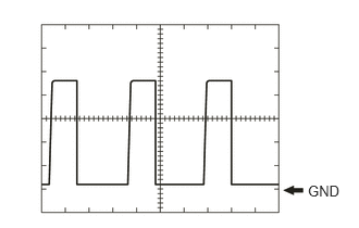
Waveform 1
| Item | Content |
|---|---|
| Tester Connection | E108-16 (NE) - E108-11 (E) |
| Tool Setting | 2 V/DIV., 2 ms./DIV. |
| Vehicle Condition | Idling (engine warmed up) |
- HINT:
-
The wavelength becomes shorter as the engine speed increases.
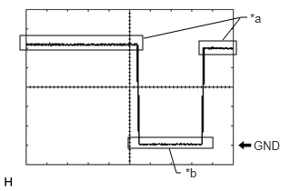
| *a | Steering lock motor not operating |
| *b | Steering lock motor operating |
Waveform 2
| Item | Content |
|---|---|
| Tester Connection | E110-29 (SLR+) - E108-11 (E) |
| Tool Setting | 2 V/DIV., 200 ms./DIV. |
| Vehicle Condition | Steering lock motor stopped →
Steering lock motor operating → Steering lock motor stopped* |
- HINT:
-
*: To check the waveform of the steering lock motor while it is operating, perform the following operations:
- ·
To operate the steering lock motor to lock the steering, open a door with the engine switch off and the shift lever in P (except Manual Transaxle).
·To operate the steering lock motor to unlock the steering, bring the electrical key transmitter sub-assembly into the cabin and turn the engine switch on (ACC) or on (IG).
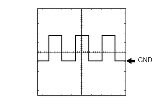
Waveform 3
| Item | Content |
|---|---|
| Tester Connection | E110-27 (SPD) - E108-11 (E) |
| Tool Setting | 5 V/DIV., 20 ms./DIV. |
| Vehicle Condition | Vehicle being driven at approx. 5 km/h (3 mph) |
- HINT:
-
The wavelength becomes shorter as the vehicle speed increases.