DOOR LOCK REAR DOOR LOCK INSPECTION
PROCEDURE

 69330
1.INSPECT REAR DOOR LOCK ASSEMBLY RH
69330
1.INSPECT REAR DOOR LOCK ASSEMBLY RH
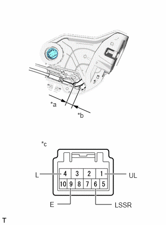
| *a | Unlock |
| *b | Lock |
| *c | Component without harness connected
(Rear Door Lock Assembly RH) |
Check the operation of the door lock motor.
Apply battery voltage and check the operation of the door lock motor.
- OK:
Battery Connection Result Battery positive (+) → Terminal 4 (L)
Battery negative (-) → Terminal 1 (UL)Locks Battery positive (+) → Terminal 1 (UL)
Battery negative (-) → Terminal 4 (L)Unlocks
If the result is not as specified, replace the rear door lock assembly RH.
Check the operation of the door unlock detection switch.
Measure the resistance according to the value(s) in the table below.
- Standard Resistance:
Tester Connection Condition Specified Condition 6 (LSSR) - 9 (E) Locked 10 kΩ or higher 6 (LSSR) - 9 (E) Unlocked Below 1 Ω
If the result is not as specified, replace the rear door lock assembly RH.
69340
2.INSPECT REAR DOOR LOCK ASSEMBLY LH
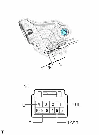
| *a | Unlock |
| *b | Lock |
| *c | Component without harness connected
(Rear Door Lock Assembly LH) |
Check the operation of the door lock motor.
Apply battery voltage and check the operation of the door lock motor.
- OK:
Battery Connection Result Battery positive (+) → Terminal 4 (L)
Battery negative (-) → Terminal 1 (UL)Locks Battery positive (+) → Terminal 1 (UL)
Battery negative (-) → Terminal 4 (L)Unlocks
If the result is not as specified, replace the rear door lock assembly LH.
Check the operation of the door unlock detection switch.
Measure the resistance according to the value(s) in the table below.
- Standard Resistance:
Tester Connection Condition Specified Condition 6 (LSSR) - 9 (E) Locked 10 kΩ or higher 6 (LSSR) - 9 (E) Unlocked Below 1 Ω
If the result is not as specified, replace the rear door lock assembly LH.