2ZR-FE BATTERY / CHARGING CHARGING SYSTEM TERMINALS OF ECM
2.531,0.354 2.927,0.594
0.396,0.24
5.906,0.354 6.302,0.594
0.396,0.24
2.615,0.396 3.063,0.677
0.448,0.281
10
false
B64
5.99,0.396 6.375,0.698
0.385,0.302
10
false
A40
- HINT:
-
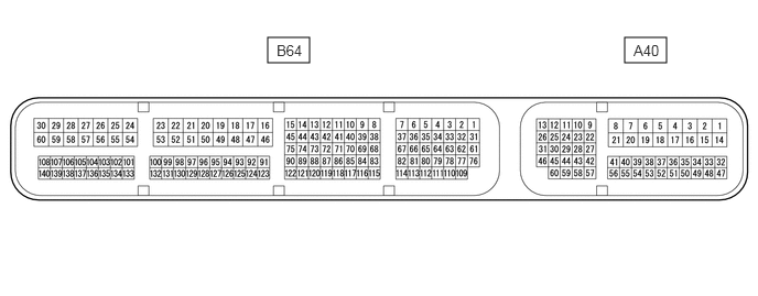
The standard normal voltage or resistance between each pair of ECM terminals is shown in the table below. The appropriate conditions for checking each pair of terminals are also indicated. The result of checks should be compared with the standard normal voltage or resistance for that pair of terminals, displayed in the Specified Condition column. The illustration above can be used as a reference to identify the ECM terminal locations.
| Terminal No. (Symbol) | Wiring Color | Terminal Description | Condition | Specified Condition |
|---|---|---|---|---|
| B64-59 (E1) - Body ground | BR - Body ground | Ground | Always | Below 1 Ω |
| A40-1 (BATT) - B64-59 (E1) | P - BR | Battery
(for measuring battery voltage and for ECM memory) |
Always | 11 to 14 V |
| B64-61 (LIN) - Body ground | L - Body ground | LIN communication line | Ignition switch off | 10 kΩ or higher |