LIGHTING (EXT) AUTOMATIC HEADLIGHT BEAM LEVEL CONTROL SYSTEM Headlight Beam Level Warning Circuit
DESCRIPTION
The headlight leveling ECU assembly sends a warning display signal to the combination meter assembly if it detects a malfunction in the headlight beam level control system. When the combination meter assembly receives the warning display signal, it alerts the driver by displaying "Headlight System Malfunction Visit Your Dealer" on the multi-information display.
WIRING DIAGRAM
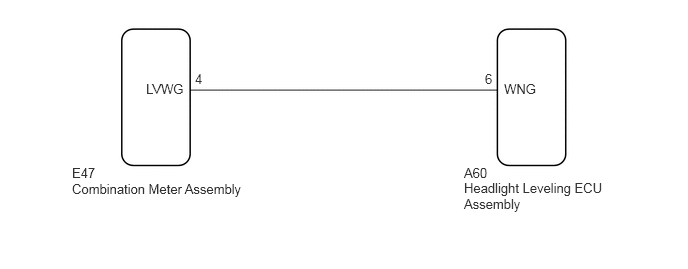
PROCEDURE
Disconnect the A60 headlight leveling ECU assembly connector.
Measure the voltage according to the value(s) in the table below.
- Standard Voltage:
Tester Connection Condition Specified Condition A60-6 (WNG) - Body ground Ignition switch ON 11 to 14 V A60-6 (WNG) - Body ground Ignition switch off Below 1 V
- Result:
Proceed to OK NG
OK
Click hereVehicle Exterior>LIGHTING (EXT)>AUTOMATIC HEADLIGHT BEAM LEVEL CONTROL SYSTEM>PROBLEM SYMPTOMS TABLE
NG
Disconnect the E47 combination meter assembly connector.
Measure the resistance according to the value(s) in the table below.
- Standard Resistance:
Tester Connection Condition Specified Condition E47-4 (LVWG) - A60-6 (WNG) Always Below 1 Ω E47-4 (LVWG) or A60-6 (WNG) - Body ground Always 10 kΩ or higher
- Result:
Proceed to OK NG
OK
Click hereVehicle Interior>METER / GAUGE / DISPLAY>METER / GAUGE SYSTEM>HOW TO PROCEED WITH TROUBLESHOOTING
NG