LIGHTING (EXT) AUTOMATIC HEADLIGHT BEAM LEVEL CONTROL SYSTEM Diagnosis Circuit
DESCRIPTION
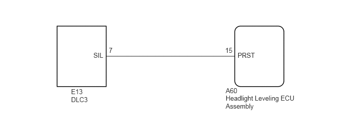
The headlight leveling ECU assembly outputs DTC information to the GTS via this circuit.
WIRING DIAGRAM
2.281,0.969 2.396,1.135
0.115,0.167
10
false
7
1.958,1.073 2.229,1.24
0.271,0.167
10
false
SIL
1.49,1.833 1.771,2.01
0.281,0.177
10
false
E13
1.49,2 1.885,2.167
0.396,0.167
10
false
DLC3
4.729,1.813 5.271,2.01
0.542,0.198
10
false
A60
4.729,1.969 6.177,2.354
1.448,0.385
10
false
Headlight Leveling ECU Assembly
4.979,1.073 5.385,1.24
0.406,0.167
10
false
PRST
4.719,0.969 4.917,1.135
0.198,0.167
10
false
15
PROCEDURE
1.CHECK HARNESS AND CONNECTOR (DLC3 - HEADLIGHT LEVELING ECU ASSEMBLY)
a.
Disconnect the A60 headlight leveling ECU assembly connector.
b.
Measure the resistance according to the value(s) in the table below.
- Standard Resistance:
Tester Connection Condition Specified Condition E13-7 (SIL) - A60-15 (PRST) Always Below 1 Ω E13-7 (SIL) or A60-15 (PRST) - Body ground Always 10 kΩ or higher
- Result:
Proceed to OK NG
OK
PROCEED TO NEXT SUSPECTED AREA SHOWN IN PROBLEM SYMPTOMS TABLE
Click hereVehicle Exterior>LIGHTING (EXT)>AUTOMATIC HEADLIGHT BEAM LEVEL CONTROL SYSTEM>PROBLEM SYMPTOMS TABLE
NG
REPAIR OR REPLACE HARNESS OR CONNECTOR