LIGHTING (EXT) AUTOMATIC HEADLIGHT BEAM LEVEL CONTROL SYSTEM TERMINALS OF ECU
CHECK HEADLIGHT LEVELING ECU ASSEMBLY

3.281,0.167 3.698,0.417
0.417,0.25
3.365,0.208 3.792,0.417
0.427,0.208
10
false
A60
a.
Disconnect the A60 headlight leveling ECU assembly connector.
b.
Measure the voltage and resistance according to the value(s) in the table below.
| Terminal No. (Symbol) | Wiring Color | Terminal Description | Condition | Specified Condition |
|---|---|---|---|---|
| A60-1 (IG) - Body ground | L - Body ground | IG power supply | Ignition switch off | Below 1 V |
| Ignition switch ON | 11 to 14 V | |||
| A60-9 (E1) - Body ground | W-B - Body ground | Ground | Always | Below 1 Ω |
c.
Connect the A60 headlight leveling ECU assembly connector.
d.
Measure the voltage, resistance and check for pulses according to the value(s) in the table below.
| Terminal No. (Symbol) | Wiring Color | Terminal Description | Condition | Specified Condition |
|---|---|---|---|---|
| A60-3 (HDLP) - Body ground | B - Body ground | Low beam headlight signal input | Low beam headlights on | Below 1.5 V |
| Low beam headlights off | 5 V or higher | |||
| A60-5 (INIT) - Body ground | Y - Body ground | Initialization signal input | Terminals LVL and GND of DLC3 connected | Below 1 V |
| Terminals LVL and GND of DLC3 not connected | 4.5 to 5.5 V | |||
| A60-6 (WNG) - Body ground | L - Body ground | Warning message drive output | Warning message displayed | Below 1 V |
| Warning message not displayed | 11 to 14 V | |||
| A60-10 (RH+) - Body ground | Y - Body ground | Headlight leveling motor RH power supply | Ignition switch off | Below 1 V |
| Ignition switch ON | 11 to 14 V | |||
| A60-11 (LH+) - Body ground | W-B - Body ground | Headlight leveling motor LH power supply | Ignition switch off | Below 1 V |
| Ignition switch ON | 11 to 14 V | |||
| A60-12 (SBR) - Body ground | SB - Body ground | Rear height control sensor sub-assembly power supply | Ignition switch off | Below 1 V |
| Ignition switch ON | 4.75 to 5.25 V | |||
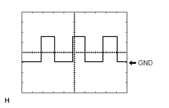
| A60-16 (SPDR) - Body ground | V - Body ground | Vehicle speed signal input | Ignition switch ON, wheel being rotated | Pulse generation
(See waveform 1) |
| A60-17 (RHT) - Body ground | G - Body ground | Headlight leveling motor RH operation signal input | With low beam headlights on, vehicle height not changed | Below 1 V |
| With low beam headlights on, vehicle height changed and maintained for more than 3 seconds | 1.0 to 14.4 V | |||
| A60-18 (LHT) - Body ground | LG - Body ground | Headlight leveling motor LH operation signal input | With low beam headlights on, vehicle height not changed | Below 1 V |
| With low beam headlights on, vehicle height changed and maintained for more than 3 seconds | 1.0 to 14.4 V | |||
| A60-19 (SHRL) - Body ground | GR - Body ground | Rear height control sensor sub-assembly signal input | Ignition switch off | Below 1 V |
| Ignition switch ON | 0.5 to 4.5 V | |||
| A60-21 (SGR) - Body ground | L - Body ground | Rear height control sensor sub-assembly ground | Always | Below 1 Ω |
| A60-23 (RH-) - Body ground | W-B - Body ground | Headlight leveling motor RH ground | Always | Below 1 Ω |
| A60-24 (LH-) - Body ground | W - Body ground | Headlight leveling motor LH ground | Always | Below 1 Ω |
i.
2.806,1.183 3.146,1.325
0.34,0.142
10
GND
Waveform 1
| Item | Content |
|---|---|
| Tester Connection | A60-16 (SPDR) - Body ground |
| Tool setting | 5 V/DIV., 20 ms./DIV. |
| Vehicle condition | Ignition switch ON, wheel being rotated |
- HINT:
-
The communication waveform changes according to the surrounding brightness.