K313 CVT CONTINUOUSLY VARIABLE TRANSAXLE SYSTEM P0717 Input/Turbine Speed Sensor "A" Circuit No Signal P07BF Input/Turbine Speed Sensor "A" Circuit Low P07C0 Input/Turbine Speed Sensor "A" Circuit High
DESCRIPTION
The ECM receives a signal from the transmission revolution sensor (NT) installed in the continuously variable transaxle to control the lock-up engagement pressure and forward and reverse clutch pressure.
The transmission revolution sensor (NT) detects the continuously variable transaxle input shaft speed and sends a signal to the ECM.
| DTC No. | Detection Item | DTC Detection Condition | Trouble Area | MIL | Memory |
|---|---|---|---|---|---|
| P0717 | Input/Turbine Speed Sensor "A" Circuit No Signal | 1. Diagnosis Condition 2. Malfunction Status 3. Malfunction Time 4. Other
1.
The vehicle is driven with the shift lever in D, the output shaft speed is 300 rpm or more, and no malfunction is detected in the park/neutral position switch assembly. 2.
The speed indicated by the transmission revolution sensor (NT) is less than 300 rpm. 3.
2 seconds 4.
1-trip detection logic |
·
Wire harness or connector ·
Continuously variable transaxle assembly (Transmission revolution sensor (NT)) ·
ECM |
Comes on | DTC stored |
| P07BF | Input/Turbine Speed Sensor "A" Circuit Low | 1. Diagnosis Condition 2. Malfunction Status 3. Malfunction Time 4. Other
1.
A transmission revolution sensor (NT) signal malfunction is not detected. 2.
The transmission revolution sensor (NT) output voltage is less than 0.2 V. 3.
2 seconds 4.
1-trip detection logic |
·
Wire harness or connector ·
Continuously variable transaxle assembly (Transmission revolution sensor (NT)) ·
ECM |
Comes on | DTC stored |
| P07C0 | Input/Turbine Speed Sensor "A" Circuit High | 1. Diagnosis Condition 2. Malfunction Status 3. Malfunction Time 4. Other
1.
A transmission revolution sensor (NT) signal malfunction is not detected. 2.
The transmission revolution sensor (NT) output voltage is higher than 1.8 V. 3.
2 seconds 4.
1-trip detection logic |
·
Wire harness or connector ·
Continuously variable transaxle assembly (Transmission revolution sensor (NT)) ·
ECM |
Comes on | DTC stored |
MONITOR DESCRIPTION
The transmission revolution sensor (NT) detects the transaxle input shaft speed. The ECM determines the necessary gear ratio based on a comparison of the transmission revolution sensor (NT) (input shaft speed) with the transmission revolution sensor (NOUT) (output shaft speed).
When the output shaft speed is higher than the expected value and the input shaft speed is less than 300 rpm while driving with the shift lever in D, the ECM will determine that the transmission revolution sensor (NT) is malfunctioning. The ECM will then illuminate the MIL and store a DTC.
WIRING DIAGRAM
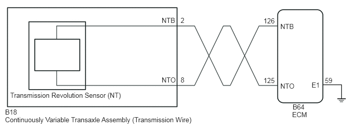
CAUTION / NOTICE / HINT
- NOTICE:
- ·
Perform initialization when parts related to the continuously variable transaxle are replaced.
Click hereDrivetrain>K313 CVT>CONTINUOUSLY VARIABLE TRANSAXLE SYSTEM>INITIALIZATION
·Check that no DTCs are stored after performing initialization.
Click hereDrivetrain>K313 CVT>CONTINUOUSLY VARIABLE TRANSAXLE SYSTEM>DTC CHECK / CLEAR
PROCEDURE
Connect the GTS to the DLC3.
Turn the ignition switch to ON.
Turn the GTS on.
Enter the following menus: Powertrain / Engine and ECT / Data List / Primary.
According to the display on the GTS, read the Data List.
- Powertrain > Engine and ECT > Data List
-
Tester Display Measurement Item Range Normal Condition Diagnostic Note SPD (NT) Input turbine speed min.: 0 rpm
max.: 12750 rpm·Equal to engine speed (NE): Lock-up ON (After warming up engine)
·Nearly equal to engine speed (NE): Lock-up OFF (Engine idling with shift lever in P or N)
·0 rpm: Vehicle stopped with shift lever in R
Data is displayed in increments of 50 rpm. NT Sensor Voltage Input turbine speed (NT) sensor output voltage min.: 0.000 V
max.: 4.999 V0.1 to 1.9 V: Engine idling (Vehicle stopped with shift lever in P or N) -
- Powertrain > Engine and ECT > Data List
-
Tester Display SPD (NT) NT Sensor Voltage - 50003 234 390,391
- Result:
Result Proceed to Data List values are not normal A Data List values are normal B
A
B
Disconnect the B18 transmission wire connector.
Disconnect the B64 ECM connector.
Measure the resistance according to the value(s) in the table below.
- Standard Resistance:
Tester Connection Condition Specified Condition B18-8 (NTO) - B64-125 (NTO) Always Below 1 Ω B18-2 (NTB) - B64-126 (NTB) Always Below 1 Ω B64-59 (E1) - Body ground Always Below 1 Ω B18-8 (NTO) or B64-125 (NTO) - Body ground and other terminals Always 10 kΩ or higher B18-2 (NTB) or B64-126 (NTB) - Body ground and other terminals Always 10 kΩ or higher
Connect the B64 ECM connector.
Connect the B18 transmission wire connector.
- Result:
Proceed to OK NG
OK
NG
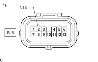
| *a | Front view of wire harness connector
(to Transmission Wire) |
Disconnect the B18 transmission wire connector.
Turn the ignition switch to ON.
Measure the voltage according to the value(s) in the table below.
- Standard Voltage:
Tester Connection Condition Specified Condition B18-2 (NTB) - Body ground Ignition switch ON 11 to 14 V
Turn the ignition switch off.
Connect the B18 transmission wire connector.
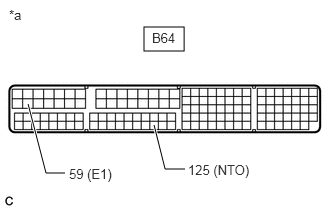
| *a | Component without harness connected
(ECM) |
Disconnect the B64 ECM connector.
Measure the resistance according to the value(s) in the table below.
- Standard Resistance:
Tester Connection Condition Specified Condition B64-125 (NTO) - B64-59 (E1) Always 99 to 101 Ω
- Result:
Proceed to OK NG
OK
NG
Replace the continuously variable transaxle assembly.
Click hereDrivetrain>K313 CVT>CONTINUOUSLY VARIABLE TRANSAXLE ASSEMBLY>COMPONENTS
- Result:
Proceed to NEXT
NEXT
Replace the ECM.
Click hereEngine / Hybrid System>2ZR-FE ENGINE CONTROL>ECM>COMPONENTS
- Result:
Proceed to NEXT
NEXT
Replace the ECM.
Click hereEngine / Hybrid System>2ZR-FE ENGINE CONTROL>ECM>COMPONENTS
- Result:
Proceed to NEXT
NEXT