DOOR LOCK POWER DOOR LOCK CONTROL SYSTEM All Doors LOCK/UNLOCK Functions do not Operate Via Door Control Switch or Door Key Cylinder
DESCRIPTION
The main body ECU (multiplex network body ECU) receives switch signals from the power window regulator master switch assembly and driver door key cylinder lock or unlock switch signals from the front door lock assembly RH. The main body ECU (multiplex network body ECU) activates the door lock motor on each door according to these signals.
WIRING DIAGRAM
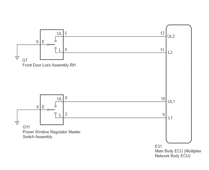
PROCEDURE
Check door lock operation.
Click hereVehicle Interior>DOOR LOCK>POWER DOOR LOCK CONTROL SYSTEM>OPERATION CHECK
- Result:
Result Proceed to All doors cannot be locked by power window regulator master switch assembly A All doors cannot be locked by driver door key cylinder B
A
B
Connect the GTS to the DLC3.
Turn the ignition switch to ON.
Turn the GTS on.
Enter the following menus: Body Electrical / Main Body / Data List.
Read the Data List according to the display on the GTS.
- Body Electrical > Main Body > Data List
-
Tester Display Measurement Item Range Normal Condition Diagnostic Note Door Lock SW-Lock Door control switch lock signal OFF or ON OFF: Lock side of door control switch not pushed
ON: Lock side of door control switch pushed- Door Lock SW-Unlock Door control switch unlock signal OFF or ON OFF: Unlock side of door control switch not pushed
ON: Unlock side of door control switch pushed-
- Body Electrical > Main Body > Data List
-
Tester Display Door Lock SW-Lock Door Lock SW-Unlock - 50003 123 17,18
- OK:
The GTS indicates ON or OFF according to the switch operations shown in the table.
- Result:
Proceed to OK NG
OK
NG
Remove the power window regulator master switch assembly.
Click hereVehicle Interior>DOOR LOCK>DOOR CONTROL SWITCH>REMOVAL
Inspect the power window regulator master switch assembly.
Click hereVehicle Interior>DOOR LOCK>DOOR CONTROL SWITCH>INSPECTION
- Result:
Proceed to OK NG
OK
NG
Disconnect the E31 main body ECU (multiplex network body ECU) connector.
Measure the resistance according to the value(s) in the table below.
- Standard Resistance:
Tester Connection Condition Specified Condition G11-2 (L) - E31-9 (L1) Always Below 1 Ω G11-8 (UL) - E31-10 (UL1) Always Below 1 Ω G11-9 (E) - Body ground Always Below 1 Ω G11-2 (L) - Body ground Always 10 kΩ or higher G11-8 (UL) - Body ground Always 10 kΩ or higher E31-9 (L1) - Body ground Always 10 kΩ or higher E31-10 (UL1) - Body ground Always 10 kΩ or higher
- Result:
Proceed to OK NG
OK
NG
Connect the GTS to the DLC3.
Turn the ignition switch to ON.
Turn the GTS on.
Enter the following menus: Body Electrical / Main Body / Data List.
Read the Data List according to the display on the GTS.
- Body Electrical > Main Body > Data List
-
Tester Display Measurement Item Range Normal Condition Diagnostic Note Door Key SW-Lock Driver door key-linked lock/unlock switch lock signal OFF or ON OFF: Driver door key cylinder not turned to lock position
ON: Driver door key cylinder turned to lock position- Door Key SW-Unlock Driver door key-linked lock/unlock switch unlock signal OFF or ON OFF: Driver door key cylinder not turned to unlock position
ON: Driver door key cylinder turned to unlock position-
- Body Electrical > Main Body > Data List
-
Tester Display Door Key SW-Lock Door Key SW-Unlock - 50003 123 19,20
- Result:
Proceed to OK NG
OK
NG
Remove the front door lock assembly RH.
Click hereVehicle Interior>DOOR LOCK>FRONT DOOR LOCK>REMOVAL
Inspect the front door lock assembly RH.
Click hereVehicle Interior>DOOR LOCK>FRONT DOOR LOCK>INSPECTION
- Result:
Proceed to OK NG
OK
NG
Disconnect the E31 main body ECU (multiplex network body ECU) connector.
Measure the resistance according to the value(s) in the table below.
- Standard Resistance:
Tester Connection Condition Specified Condition G7-6 (L) - E31-11 (L2) Always Below 1 Ω G7-5 (UL) - E31-12 (UL2) Always Below 1 Ω G7-8 (E) - Body ground Always Below 1 Ω G7-6 (L) - Body ground Always 10 kΩ or higher G7-5 (UL) - Body ground Always 10 kΩ or higher E31-11 (L2) - Body ground Always 10 kΩ or higher E31-12 (UL2) - Body ground Always 10 kΩ or higher
- Result:
Proceed to OK NG
OK
NG