DOOR LOCK WIRELESS DOOR LOCK CONTROL SYSTEM(w/ Smart Entry and Start System) B1242 Wireless Door Lock Tuner Circuit Malfunction
DESCRIPTION
The door control with receiver ECU assembly is used to receive radio waves related to the entry functions of the electrical key transmitter sub-assembly. The certification ECU (smart key ECU assembly) decodes the requested electrical key transmitter sub-assembly operation by identifying a key code based on the radio waves received via the door control with receiver ECU assembly. The door control with receiver ECU assembly receives a signal from the electrical key transmitter sub-assembly and sends signals to the main body ECU (multiplex network body ECU) through the certification ECU (smart key ECU assembly) (ex. if a door lock operation is requested, the certification ECU (smart key ECU assembly) sends a door lock command to the main body ECU (multiplex network body ECU)).
| DTC No. | Detection Item | DTC Detection Condition | Trouble Area |
|---|---|---|---|
| B1242 | Wireless Door Lock Tuner Circuit Malfunction | ·
Short in RDAM to ground between the certification ECU (smart key ECU assembly) and door control with receiver ECU assembly. ·
Short in RDAM to ground when RCO (5 V) output from the ECU is off. |
·
Wire harness or connector ·
Door control with receiver ECU assembly ·
Certification ECU (smart key ECU assembly) |
WIRING DIAGRAM
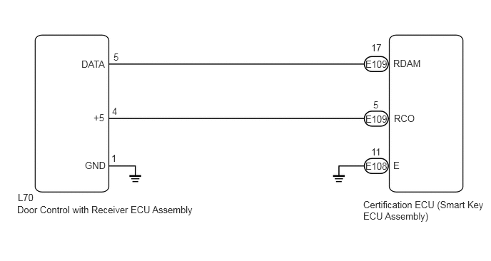
CAUTION / NOTICE / HINT
- NOTICE:
- ·
When replacing or inspecting the door control with receiver ECU assembly and wire harness, do not change the position or length of the wire harness. If the wire harness is too close to the door control with receiver ECU assembly, entry and wireless function performance may be affected.
·This DTC is not stored within 10 seconds of the engine switch being turned from on (IG) to off.
·Before replacing the certification ECU (smart key ECU assembly), refer to Service Bulletin.
PROCEDURE
Disconnect the L70 door control with receiver ECU assembly connector.
Measure the voltage and resistance and check for pulses according to the value(s) in the table below.
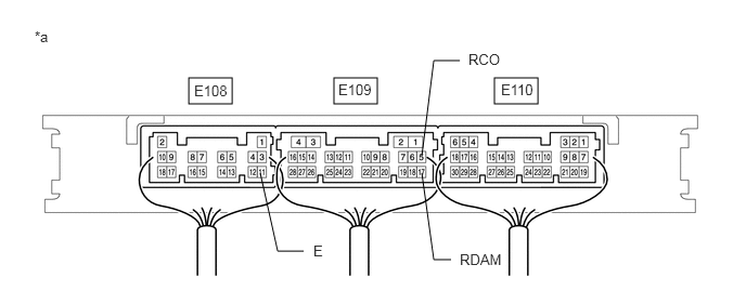
| *a | Component with harness connected
(Certification ECU (Smart Key ECU Assembly)) |
- | - |
- Standard Voltage:
Tester Connection Condition Specified Condition E109-5 (RCO) - E108-11 (E) Always Below 1 V → 4.5 to 5.5 V
(Pulse generation)E109-17 (RDAM) - E108-11 (E) Always 11 to 14 V
- Standard Resistance:
Tester Connection Condition Specified Condition E108-11 (E) - Body ground Always Below 1 Ω
- Result:
Result OK NG
OK
NG
Disconnect the E109 certification ECU (smart key ECU assembly) connector.
Measure the resistance according to the value(s) in the table below.
- Standard Resistance:
Tester Connection Condition Specified Condition E109-17 (RDAM) - L70-5 (DATA) Always Below 1 Ω E109-5 (RCO) - L70-4 (+5) Always Below 1 Ω L70-1 (GND) - Body ground Always Below 1 Ω E109-17 (RDAM) or L70-5 (DATA) - Body ground Always 10 kΩ or higher E109-5 (RCO) or L70-4 (+5) - Body ground Always 10 kΩ or higher
- Result:
Proceed to OK NG
OK
NG