NETWORKING CAN COMMUNICATION SYSTEM SYSTEM DIAGRAM
OVERALL CAN BUS DIAGRAM
a.
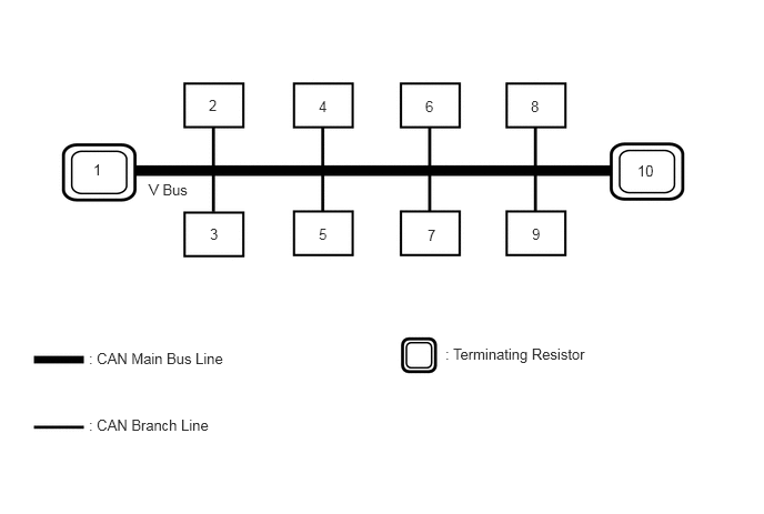
The CAN communication system is composed of 1 bus.
0.875,1.51 1.031,1.708
0.156,0.198
10
false
1
1.958,0.906 2.115,1.104
0.156,0.198
10
false
2
1.969,2.115 2.344,2.479
0.375,0.365
10
false
3
2.99,0.917 3.146,1.115
0.156,0.198
10
false
4
2.99,2.115 3.25,2.406
0.26,0.292
10
false
5
3.99,0.917 4.146,1.115
0.156,0.198
10
false
6
4.01,2.125 4.167,2.323
0.156,0.198
10
false
7
4.979,0.917 5.135,1.115
0.156,0.198
10
false
8
4.99,2.115 5.146,2.313
0.156,0.198
10
false
9
5.979,1.521 6.25,1.75
0.271,0.229
10
false
10
1.396,1.698 2.021,2.094
0.625,0.396
10
false
V Bus
0.833,3.281 2.521,3.542
1.688,0.26
10
false
: CAN Main Bus Line
0.833,3.906 2.521,4.167
1.688,0.26
10
false
: CAN Branch Line
4.177,3.24 5.865,3.5
1.688,0.26
10
false
: Terminating Resistor
| 1 | ECM | 2 | Main Body ECU (Multiplex Network Body ECU) |
| 3 | Air Conditioning Amplifier Assembly | 4 | Power Steering ECU Assembly |
| 5 | DLC3 | 6 | Skid Control ECU (Brake Actuator Assembly)
(w/ ABS) |
| 7 | Airbag ECU Assembly | 8 | Steering Sensor
(w/ VSC) |
| 9 | Certification ECU (Smart Key ECU Assembly)
(w/ Smart Entry and Start System) |
10 | Combination Meter Assembly |
- HINT:
-
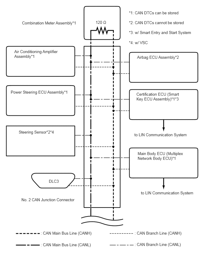
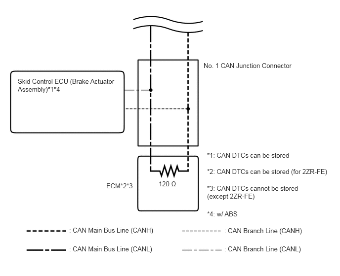
Refer to the following bus wiring diagrams for details.
V BUS
0.771,0.719 2.76,1.031
1.99,0.313
10
false
Combination Meter Assembly*1
3.344,0.698 3.927,0.948
0.583,0.25
10
false
120 Ω
4.51,0.365 6.5,0.677
1.99,0.313
10
false
*1: CAN DTCs can be stored
4.51,0.708 6.5,1.021
1.99,0.313
10
false
*2: CAN DTCs cannot be stored
4.51,1.052 7.094,1.292
2.583,0.24
10
false
*3: w/ Smart Entry and Start System
0.5,1.719 2.073,2.177
1.573,0.458
10
false
Air Conditioning Amplifier Assembly*1
0.75,6.896 2.74,7.208
1.99,0.313
10
false
No. 2 CAN Junction Connector
4.792,1.917 6.396,2.188
1.604,0.271
10
false
Airbag ECU Assembly*2
0.375,3.135 2.51,3.396
2.135,0.26
10
false
Power Steering ECU Assembly*1
0.656,4.531 2.26,4.802
1.604,0.271
10
false
Steering Sensor*2*4
4.813,5.281 6.469,5.729
1.656,0.448
10
false
Main Body ECU (Multiplex Network Body ECU)*1
4.771,3.208 6.313,3.698
1.542,0.49
10
false
Certification ECU (Smart Key ECU Assembly)*1*3
4.51,1.406 7.094,1.646
2.583,0.24
10
false
*4: w/ VSC
4.927,6.656 6.948,6.917
2.021,0.26
10
false
to LIN Communication System
1.708,6.25 2.26,6.469
0.552,0.219
10
false
DLC3
1.427,8.063 3.417,8.375
1.99,0.313
10
false
: CAN Main Bus Line (CANH)
1.427,8.469 3.417,8.781
1.99,0.313
10
false
: CAN Main Bus Line (CANL)
4.708,8.063 6.698,8.375
1.99,0.313
10
false
: CAN Branch Line (CANH)
4.708,8.458 6.698,8.771
1.99,0.313
10
false
: CAN Branch Line (CANL)
4.698,4.625 6.719,4.885
2.021,0.26
10
false
to LIN Communication System
4.729,5.177 6.531,5.406
1.802,0.229
10
false
: CAN Branch Line (CANL)
4.729,4.792 6.531,5.021
1.802,0.229
10
false
: CAN Branch Line (CANH)
1.458,4.781 3.375,5.031
1.917,0.25
10
false
: CAN Main Bus Line (CANH)
1.458,5.177 3.375,5.427
1.917,0.25
10
false
: CAN Main Bus Line (CANL)
4.292,1.302 6.281,1.667
1.99,0.365
10
false
No. 1 CAN Junction Connector
0.375,1.635 2.49,2.323
2.115,0.688
10
false
Skid Control ECU (Brake Actuator Assembly)*1*4
2.24,3.844 3.104,4.042
0.865,0.198
10
false
ECM*2*3
3.344,3.802 4.115,4.042
0.771,0.24
10
false
120 Ω
4.365,3.198 6.25,3.542
1.885,0.344
10
false
*1: CAN DTCs can be stored
4.365,3.542 6.979,3.906
2.615,0.365
10
false
*2: CAN DTCs can be stored (for 2ZR-FE)
4.365,3.896 6.344,4.448
1.979,0.552
10
false
*3: CAN DTCs cannot be stored (except 2ZR-FE)
4.365,4.438 5.344,4.708
0.979,0.271
10
false
*4: w/ ABS
- HINT:
-
The CAN communication system connects to other networks via ECUs that function as a gateway.
-
Click herePower Source / Network>NETWORKING>LIN COMMUNICATION SYSTEM>SYSTEM DIAGRAM