2NZ-FE ENGINE MECHANICAL  CYLINDER BLOCK  REPLACEMENT  


PROCEDURE

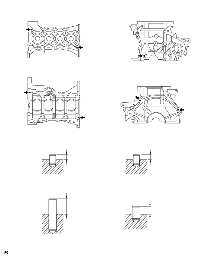
Hide 11434C 1.REPLACE STRAIGHT PIN

NOTICE:

It is not necessary to remove the straight pins unless they are being replaced.


a.

Remove the 7 straight pins.


b.

Using a plastic hammer, tap in 7 new straight pins to the specified protrusion height.
A154883
0.75,0.917 0.875,1.073 0.125,0.156 10 false A 2.896,1.521 3.021,1.677 0.125,0.156 10 false A 0.698,3.083 0.823,3.24 0.125,0.156 10 false B 2.969,3.948 3.094,4.104 0.125,0.156 10 false B 4.625,1.813 4.75,1.969 0.125,0.156 10 false C 6.385,3.677 6.51,3.833 0.125,0.156 10 false D 4.552,3.198 4.677,3.354 0.125,0.156 10 false D 2.365,5.302 3.656,5.719 1.292,0.417 10 false 8.5 to 9.5 mm 2.365,7 3.594,7.396 1.229,0.396 10 false 18.5 to 19.5 mm 5.26,5.313 6.396,5.667 1.135,0.354 10 false 8.5 to 9.5 mm 5.25,7.135 6.469,7.479 1.219,0.344 10 false 11.5 to 12.5 mm 1.781,6.052 2.385,6.417 0.604,0.365 10 false A 4.688,6.073 5.146,6.333 0.458,0.26 10 false B 1.792,8.177 2.229,8.521 0.438,0.344 10 false C 4.646,7.99 5.146,8.302 0.5,0.313 10 false D 5.323,0.385 5.521,0.573 0.198,0.188 10 false *b 5.323,2.354 5.521,2.542 0.198,0.188 10 false *d 1.833,2.354 2.031,2.542 0.198,0.188 10 false *c 1.833,0.385 2.031,0.573 0.198,0.188 10 false *a 1.74,5.094 2.052,5.292 0.313,0.198 10 false *e 4.615,5.104 4.927,5.302 0.313,0.198 10 false *e 1.74,6.552 2.052,6.75 0.313,0.198 10 false *f 4.625,6.865 4.938,7.063 0.313,0.198 10 false *f
*a Upper Side *b Front Side
*c Lower Side *d Rear Side
*e Diameter 8.0 mm (0.315 in.) *f Diameter 10 mm (0.394 in.)


Standard Protrusion:
Pin (A):

8.5 to 9.5 mm (0.335 to 0.374 in.)

Pin (B):

8.5 to 9.5 mm (0.335 to 0.374 in.)

Pin (C):

18.5 to 19.5 mm (0.728 to 0.768 in.)

Pin (D):

11.5 to 12.5 mm (0.453 to 0.492 in.)


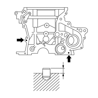
Hide 15100A 2.REPLACE OIL PUMP SET RING PIN

NOTICE:

It is not necessary to remove the oil pump set ring pins unless they are being replaced.


a.

Remove the 2 oil pump set ring pins.


b.
A290581
2.313,2.406 2.625,2.604 0.313,0.198 10 false *a
*a Protrusion Height


Using a plastic hammer, tap in 2 new oil pump set ring pins.

Standard Protrusion:

3.5 to 4.5 mm (0.138 to 0.177 in.)


Hide 15104E 3.REPLACE STUD BOLT

NOTICE:

If a stud bolt is deformed or the threads are damaged, replace it.


a.

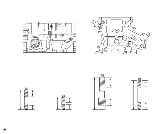
Using an E5 and E6 "TORX" socket wrench, remove the 7 stud bolts.


b.

Using an E5 and E6 "TORX" socket wrench, install the 7 stud bolts.
A154884
1.396,2.052 2.031,2.604 2.031,2.604 1.677,1.688 false 1.448,1.583 1.104,0.646 1.104,0.646 1.604,1.615 false 2.24,1.125 2.448,0.792 false 5.688,1.781 6.531,1.063 6.531,1.063 6.302,2.063 false 2.021,2.635 2.323,2.938 0.302,0.302 10 false A 0.938,0.563 1.271,0.875 0.333,0.313 10 false B 2.5,0.698 2.885,0.99 0.385,0.292 10 false C 6.604,0.948 6.917,1.396 0.313,0.448 10 false D 1.104,4.917 1.406,5.323 0.302,0.406 10 false A 2.729,4.917 2.969,5.219 0.24,0.302 10 false B 4.427,4.917 4.885,5.26 0.458,0.344 10 false C 6.063,4.896 6.469,5.396 0.406,0.5 10 false D 4.917,4.333 5.313,4.677 0.396,0.344 10 false *k 5.594,4.031 6,4.375 0.406,0.344 10 false *l 6.531,3.604 6.927,3.948 0.396,0.344 10 false *d 6.51,4.531 6.906,4.875 0.396,0.344 10 false *d 2.042,0.375 2.354,0.531 0.313,0.156 10 false *a 4.99,0.375 5.302,0.531 0.313,0.156 10 false *b 0.594,4.271 0.906,4.427 0.313,0.156 10 false *c 1.552,3.969 1.865,4.125 0.313,0.156 10 false *d 1.573,4.594 1.885,4.75 0.313,0.156 10 false *e 2.229,4.417 2.542,4.573 0.313,0.156 10 false *f 3.198,4.25 3.563,4.5 0.365,0.25 10 false *g 3.188,4.583 3.5,4.74 0.313,0.156 10 false *h 3.854,3.969 4.167,4.125 0.313,0.156 10 false *i 4.958,3.469 5.396,3.823 0.438,0.354 10 false *j
*a LH Side *b Front Side
*c 29 mm (1.14 in.) *d 12 mm (0.472 in.)
*e 9 mm (0.354 in.) *f 18 mm (0.709 in.)
*g 8.5 mm (0.335 in.) *h 8 mm (0.315 in.)
*i 48 mm (1.89 in.) *j 15 mm (0.591 in.)
*k 10 mm (0.394 in.) *l 43.5 mm (1.71 in.)


Torque:
Bolt (A), (B) and (D) : 5.0 N*m (51 kgf*cm, 44 in.*lbf)
Bolt (C) : 11 N*m (112 kgf*cm, 8 ft.*lbf)

NOTICE:

The lower threads of the bolt are installed into the cylinder block sub-assembly.