2NZ-FE ENGINE MECHANICAL CYLINDER BLOCK REASSEMBLY
PROCEDURE

 1.INSTALL OIL JET
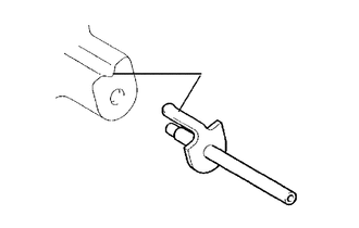
| *a | Align |
Align the groove on the cylinder block sub-assembly with the oil jet positioning bracket and tap in the oil jet.
- NOTICE:
-
Do not tap the tip of the oil jet.

 11432A
2.INSTALL NO. 1 WITH HEAD TAPER SCREW PLUG
Clean and degrease the No. 1 with head taper screw plug and installation hole.
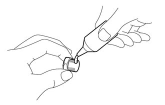
| *a | Adhesive |
Apply adhesive to the end 2 or 3 threads of the No. 1 with head taper screw plug.
- Adhesive:
Toyota Genuine Adhesive 1324, Three Bond 1324 or equivalent
- NOTICE:
-
To prevent contamination by foreign matter, install immediately after applying adhesive.
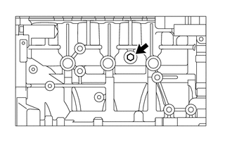
Install the No. 1 with head taper screw plug to the cylinder block sub-assembly.
- Torque:
- 30 N*m (306 kgf*cm, 22 ft.*lbf)
- NOTICE:
-
Do not add engine coolant for at least 1 hour after installation.

 11711
3.INSTALL CRANKSHAFT BEARING
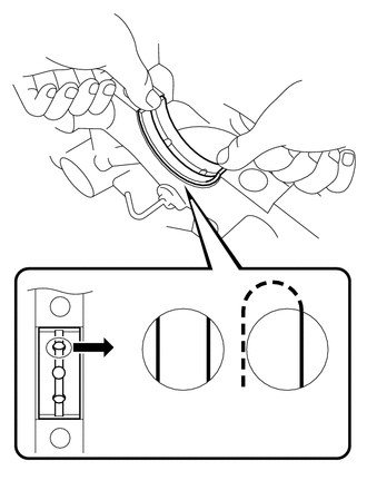
| *a | Correct |
| *b | Incorrect |
Align the upper crankshaft bearings with the oil hole of the cylinder block sub-assembly and install the upper crankshaft bearings.
- NOTICE:
-
Do not apply engine oil to the crankshaft bearings or the contact surfaces.
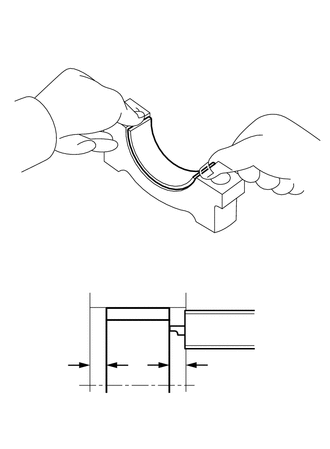
| *a | Vernier Caliper |
Install the lower crankshaft bearings to the crankshaft bearing caps.
Using a vernier caliper, measure the distance between the crankshaft bearing cap edge and the lower crankshaft bearing edge.
- Difference between (A) and (B):
0.7 mm (0.0276 in.) or less
- NOTICE:
-
Do not apply engine oil to the crankshaft bearings or the contact surfaces.

 11791
4.INSTALL UPPER CRANKSHAFT THRUST WASHER
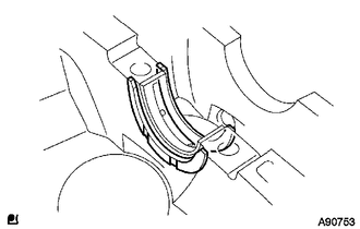
| *a | Oil Grooves |
Install the 2 upper crankshaft thrust washers to the No. 3 journal position of the cylinder block sub-assembly with the oil grooves facing outward.
Apply engine oil to the upper crankshaft thrust washers.

 13411
5.INSTALL CRANKSHAFT
Install the crankshaft to the cylinder block sub-assembly.
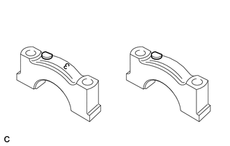
| *a | No. 3 Crankshaft Bearing Cap |
| *b | No. 1, 2, 4, 5 Crankshaft Bearing Cap |
| *c | Front Mark |
| *d | Number |
| *e | Front Mark and Number |
Examine the front marks and numbers and install the crankshaft bearing caps onto the cylinder block sub-assembly.
Apply a light coat of engine oil to the threads of the crankshaft bearing cap set bolts.
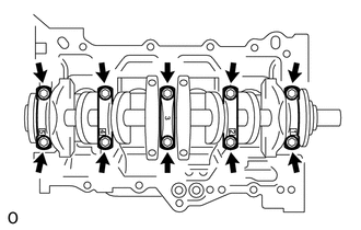
Step 1
Uniformly tighten the 10 crankshaft bearing cap set bolts in the order shown in the illustration.
- Torque:
- 22 N*m (224 kgf*cm, 16 ft.*lbf)
- NOTICE:
-
Check that the crankshaft turns smoothly.
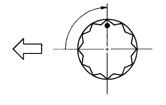
| *a | Paint Mark |

|
Engine Front |
Step 2
Mark the front of the crankshaft bearing cap set bolts with paint.
Further tighten the crankshaft bearing cap set bolts by 90° in the order shown in step 1.
Check that the paint marks are now at a 90° angle to the front.
Check that the crankshaft turns smoothly.

 11791
6.INSPECT CRANKSHAFT THRUST CLEARANCE

 13101
7.INSTALL PISTON SUB-ASSEMBLY WITH PIN
Coat the piston pin and pin holes in the piston with engine oil.
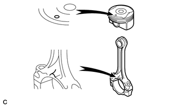
| *a | Front Mark |
Align the cavity of the piston with the protruding portion on the connecting rod.
Using SST, press in the piston pin.
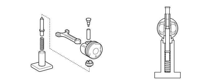
| *1 | Piston Pin | *2 | Connecting Rod Sub-assembly |
| *3 | Piston | - | - |
- SST
- 09221-25026 (09221-00021, 09221-00030, 09221-00150, 09221-00090, 09221-00100)
- NOTICE:
- ·
The piston and piston pin are a matched set.
·With the connecting rod fully inserted into the piston end, press in the piston pin until it is flush with the piston surface.
Check the fitting condition between the piston and piston pin by trying to move the piston back and forth on the piston pin.

 13041
8.INSTALL CONNECTING ROD BEARING
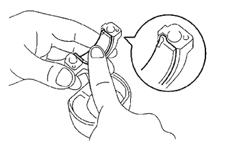
| *a | Claw |
Align the connecting rod bearing claw with the groove of the connecting rod or connecting rod cap.
- NOTICE:
-
Clean the back side of the connecting rod bearing and the connecting rod bearing surface of the connecting rod and keep them free of oil.

 13011
9.INSTALL PISTON RING SET
- HINT:
-
When reusing the piston rings, install them onto the matched pistons in the correct orientation.
Install the expander and 2 side rails by hand.
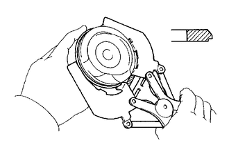
| *a | No. 2 Compression Ring |
Using a piston ring expander, install the No. 1 compression ring and No. 2 compression ring as shown in the illustration.
- HINT:
-
The No. 1 compression ring can be installed with either side facing upward.
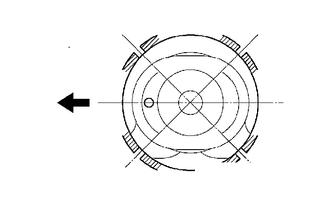
| *a | No. 1 Compression Ring and Expander |
| *b | Lower Side Rail |
| *c | Upper Side Rail |
| *d | No. 2 Compression Ring |

|
Engine Front |
Position the piston ring set so that the ring ends are as shown in the illustration.

 10.INSTALL PISTON SUB-ASSEMBLY WITH CONNECTING ROD
Apply engine oil to the cylinder walls, the pistons, and the surfaces of connecting rod bearings.
Check the position of the piston ring ends.
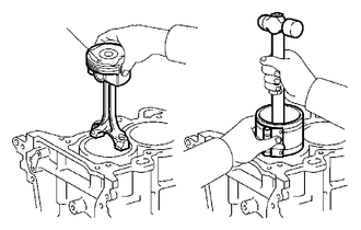
| *a | Front Mark |
Using a piston ring compressor, push the correctly numbered piston sub-assembly with connecting rod into the cylinder with the front mark of the piston facing forward.
- NOTICE:
- ·
Clean the back side of the connecting rod bearing and the connecting rod bearing surface of the connecting rod cap and keep them free of oil.
·Match the numbered connecting rod cap with the connecting rod.
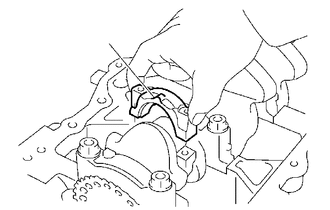
| *a | Front Mark |
Make sure that the connecting rod and connecting rod cap are in the correct combination and that the front mark of the connecting rod cap is facing in the correct direction, then install the connecting rod cap onto the connecting rod.
Apply a light coat of engine oil to the threads of the connecting rod bolts.
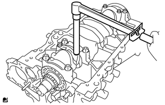
Step 1
Using SST, tighten the connecting rod bolts in several steps to the specified torque.
- SST
- 09205-16011
- Torque:
- 15 N*m (153 kgf*cm, 11 ft.*lbf)

| *a | Paint Mark |

|
Engine Front |
Step 2
Mark the front of the connecting rod bolts with paint.
Further tighten the connecting rod bolts by 90° in the order shown in step 1.
Check that the crankshaft turns smoothly.

 11.INSPECT CONNECTING ROD THRUST CLEARANCE