U340E AUTOMATIC TRANSMISSION / TRANSAXLE AUTOMATIC TRANSAXLE SYSTEM P2759 Torque Converter Clutch Pressure Control Solenoid Control Circuit Electrical (Shift Solenoid Valve SLU)
DESCRIPTION
The ECM uses the signals from the throttle position sensor, transmission revolution sensor, vehicle speed sensor and crankshaft position sensor to the monitor the engagement condition of the lock-up clutch.
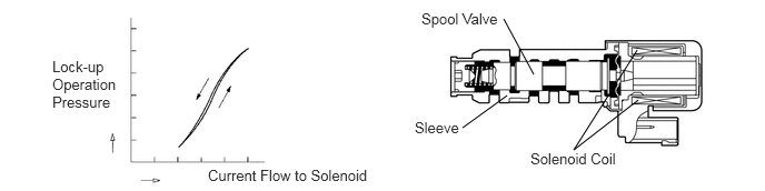
The ECM compares the engagement condition of the lock-up clutch with the lock-up schedule in the ECM memory to detect mechanical problems of the shift solenoid valve SLU, valve body and torque converter assembly.
| DTC No. | Detection Item | DTC Detection Condition | Trouble Area | MIL | Memory |
|---|---|---|---|---|---|
| P2759 | Torque Converter Clutch Pressure Control Solenoid Control Circuit Electrical (Shift Solenoid Valve SLU) | Open or short is detected in shift solenoid valve SLU circuit for 1 second or more while driving (1-trip detection logic) | ·
Open or short in shift solenoid valve SLU circuit ·
Shift solenoid valve SLU ·
ECM |
Comes on | DTC stored |
MONITOR DESCRIPTION
When an open or short in the shift solenoid valve SLU circuit is detected, the ECM interprets this as a fault. The ECM will illuminate the MIL and store this DTC.
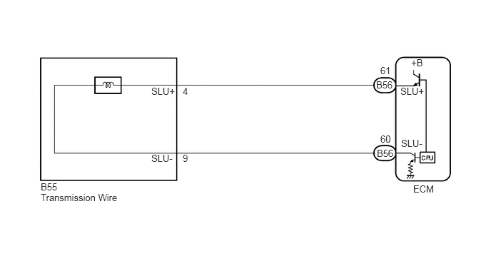
WIRING DIAGRAM
CAUTION / NOTICE / HINT
- NOTICE:
-
Perform initialization when parts related to the automatic transaxle are replaced.
-
Click hereDrivetrain>U340E AUTOMATIC TRANSMISSION / TRANSAXLE>AUTOMATIC TRANSAXLE SYSTEM>PRECAUTION
PROCEDURE
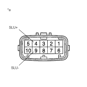
| *a | Component without harness connected
(Transmission Wire) |
Disconnect the transmission wire connector from the transaxle.
Measure the resistance according to the value(s) in the table below.
- Standard Resistance:
Tester Connection Condition Specified Condition 4 (SLU+) - 9 (SLU-) 20°C (68°F) 5.0 to 5.6 Ω
Measure the resistance according to the value(s) in the table below.
- Standard Resistance (Check for short):
Tester Connection Condition Specified Condition 4 (SLU+) - Body ground Always 10 kΩ or higher 9 (SLU-) - Body ground Always 10 kΩ or higher
- Result:
Proceed to OK NG
OK
NG
Connect the transmission wire connector to the transaxle.
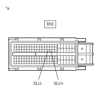
| *a | Front view of wire harness connector
(to ECM) |
Disconnect the ECM connector.
Measure the resistance according to the value(s) in the table below.
- Standard Resistance:
Tester Connection Condition Specified Condition B56-61 (SLU+) - B56-60 (SLU-) 20°C (68°F) 5.0 to 5.6 Ω
Measure the resistance according to the value(s) in the table below.
- Standard Resistance (Check for short):
Tester Connection Condition Specified Condition B56-61 (SLU+) - Body ground Always 10 kΩ or higher B56-60 (SLU-) - Body ground Always 10 kΩ or higher
- Result:
Proceed to OK NG
OK
NG
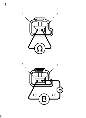
| *1 | Shift Solenoid Valve SLU |
Remove the shift solenoid valve SLU.
Measure the resistance according to the value(s) in the table below.
- Standard Resistance:
Tester Connection Condition Specified Condition 1 - 2 20°C (68°F) 5.0 to 5.6 Ω
Connect a battery positive (+) lead with a 21 W bulb to terminal 2 and a negative (-) lead to terminal 1 of the solenoid valve connector, then check that the valve moves and makes an operating sound.
- OK:
Valve moves and makes an operating sound.
- Result:
Proceed to OK NG
OK
NG