U340E AUTOMATIC TRANSMISSION / TRANSAXLE AUTOMATIC TRANSAXLE SYSTEM P0973 Shift Solenoid "A" Control Circuit Low (Shift Solenoid Valve S1) P0974 Shift Solenoid "A" Control Circuit High (Shift Solenoid Valve S1)
DESCRIPTION
Shifting from 1st to 4th is performed through the "ON" and "OFF" operation of the shift solenoid valves S1 and S2 controlled by the ECM. If an open or short circuit occurs in either of the solenoid valves, the ECM controls the remaining normal solenoid valve to allow the vehicle to be operated smoothly (fail safe function).
| DTC No. | Detection Item | DTC Detection Condition | Trouble Area | MIL | Memory |
|---|---|---|---|---|---|
| P0973 | Shift Solenoid "A" Control Circuit Low (Shift Solenoid Valve S1) | ECM detects short in solenoid valve S1 circuit 2 times when solenoid valve S1 is operated (1-trip detection logic) | ·
Short in shift solenoid valve S1 circuit ·
Shift solenoid valve S1 ·
ECM |
Comes on | DTC stored |
| P0974 | Shift Solenoid "A" Control Circuit High (Shift Solenoid Valve S1) | ECM detects open in solenoid valve S1 circuit 2 times when solenoid valve S1 is not operated (1-trip detection logic) | ·
Open in shift solenoid valve S1 circuit ·
Shift solenoid valve S1 ·
ECM |
Comes on | DTC stored |
MONITOR DESCRIPTION
The ECM commands gear shifts by turning the shift solenoid valves "ON/OFF". When there is an open or short circuit in any shift solenoid valve circuit, the ECM detects the problem, illuminates the MIL and stores a DTC. The ECM performs the fail-safe function and turns the remaining normal shift solenoid valves "ON/OFF". (In the case of an open or short circuit, the ECM stops sending current to the circuit.)
Click hereDrivetrain>U340E AUTOMATIC TRANSMISSION / TRANSAXLE>AUTOMATIC TRANSAXLE SYSTEM>FAIL-SAFE CHART
WIRING DIAGRAM
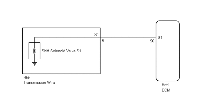
CAUTION / NOTICE / HINT
- NOTICE:
-
Perform initialization when parts related to the automatic transaxle are replaced.
-
Click hereDrivetrain>U340E AUTOMATIC TRANSMISSION / TRANSAXLE>AUTOMATIC TRANSAXLE SYSTEM>PRECAUTION
PROCEDURE
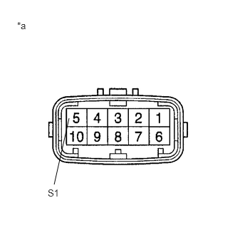
| *a | Component without harness connected
(Transmission Wire) |
Disconnect the transmission wire connector from the transaxle.
Measure the resistance according to the value(s) in the table below.
- Standard Resistance:
Tester Connection Condition Specified Condition 5 (S1) - Body ground 20°C (68°F) 11 to 15 Ω
- Result:
Proceed to OK NG
OK
NG
Connect the transmission wire connector to the transaxle.
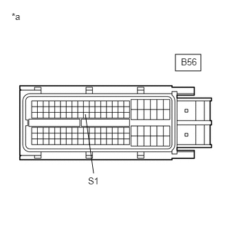
| *a | Front view of wire harness connector
(to ECM) |
Disconnect the ECM connector.
Measure the resistance according to the value(s) in the table below.
- Standard Resistance:
Tester Connection Condition Specified Condition B56-56 (S1) - Body ground 20°C (68°F) 11 to 15 Ω
- Result:
Proceed to OK NG
OK
NG
Remove the shift solenoid valve S1.
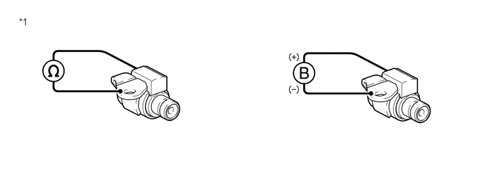
| *1 | Shift Solenoid Valve S1 | - | - |
Measure the resistance according to the value(s) in the table below.
- Standard Resistance:
Tester Connection Condition Specified Condition Solenoid Connector (S1) - Solenoid Body (S1) 20°C (68°F) 11 to 15 Ω
Connect a battery positive (+) lead to the terminal of the solenoid connector, and a negative (-) lead to the solenoid body.
- OK:
The solenoid makes an operating sound.
- Result:
Proceed to OK NG
OK
NG