U340E AUTOMATIC TRANSMISSION / TRANSAXLE AUTOMATIC TRANSAXLE SYSTEM P0705 Transmission Range Sensor Circuit Malfunction (PRNDL Input)
DESCRIPTION
The park/neutral position switch detects the shift lever position and sends signals to the ECM.
| DTC No. | Detection Item | DTC Detection Condition | Trouble Area | MIL | Memory |
|---|---|---|---|---|---|
| P0705 | Transmission Range Sensor Circuit Malfunction (PRNDL Input) | One of the following conditions (A), (B), (C) or (D) is met:
(A) Any 2 or more signals of the following are ON simultaneously (2-trip detection logic) ·
NSW input signal ·
R input signal ·
D input signal ·
2 input signal ·
L input signal (B) Any 2 or more signals of the following are ON simultaneously (2-trip detection logic) ·
P input signal ·
R input signal ·
N input signal ·
D input signal ·
2 input signal ·
L input signal (C) All switches are OFF simultaneously for P, R, N, D, 2 and L positions (2-trip detection logic) (D) Both 1 and 2 are met (2-trip detection logic) 1.
One of following is met 1.
NSW input signal 2.
P input signal 3.
R input signal 4.
N input signal 2.
One of following is ON. 1.
3 input signal |
·
Open or short in park/neutral position switch assembly circuit ·
Park/neutral position switch assembly ·
ECM |
Comes on | DTC stored |
MONITOR DESCRIPTION
The park/neutral position switch detects the gearshift position and sends a signal to the ECM.
For security, the park/neutral position switch detects the gearshift position so that engine can be started only when the shift lever is in P or N.
When the park/neutral position switch sends more than one signal at a time from switch positions P, R, N, D, 3, 2 or L the ECM interprets this as a fault in the switch. The ECM will illuminate the MIL and store this DTC.
WIRING DIAGRAM
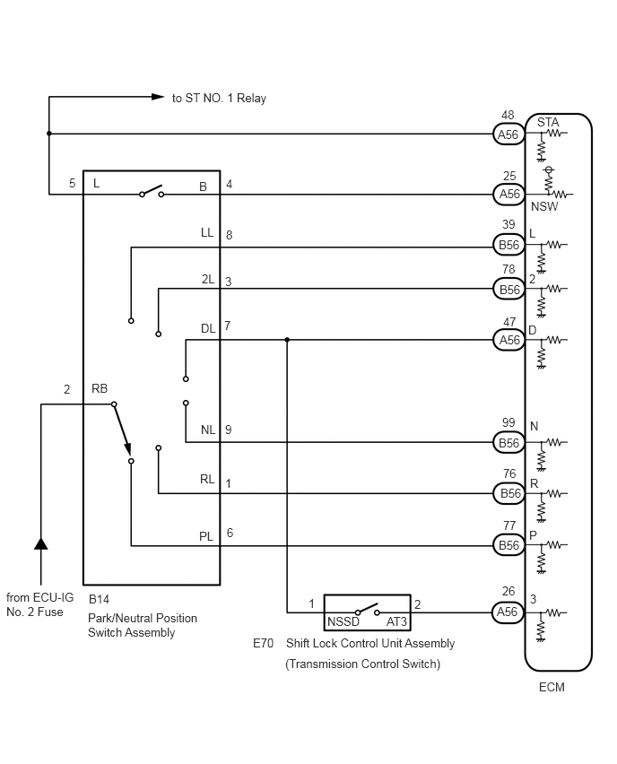
CAUTION / NOTICE / HINT
- NOTICE:
-
Perform initialization when parts related to the automatic transaxle are replaced.
-
Click hereDrivetrain>U340E AUTOMATIC TRANSMISSION / TRANSAXLE>AUTOMATIC TRANSAXLE SYSTEM>PRECAUTION
PROCEDURE
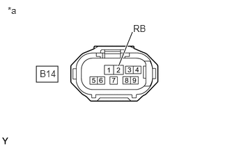
| *a | Front view of wire harness connector
(to Park/Neutral Position Switch Assembly) |
Disconnect the park/neutral position switch assembly connector.
Measure the voltage according to the value(s) in the table below.
- Standard Voltage:
Tester Connection Condition Specified Condition B14-2 (RB) - Body ground Ignition switch ON 11 to 14 V Ignition switch off Below 1 V
- Result:
Proceed to OK NG
OK
NG
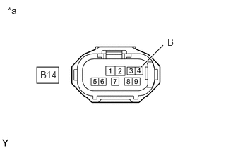
| *a | Front view of wire harness connector
(to Park/Neutral Position Switch Assembly) |
Measure the voltage according to the value(s) in the table below.
- Standard Voltage:
Tester Connection Condition Specified Condition B14-4 (B) - Body ground Ignition switch ON 11 to 14 V Ignition switch off Below 1 V
- Result:
Proceed to OK NG
OK
NG
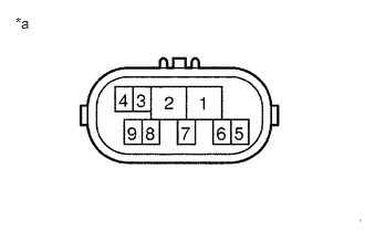
| *a | Component without harness connected
(Park/Neutral Position Switch Assembly) |
Measure resistance according to the value(s) in the table below when the shift lever is moved to each position.
- Standard Resistance:
Tester Connection Condition Specified Condition 2 - 6 and 4 - 5 Shift lever in P Below 1 Ω Shift lever not in P 10 kΩ or higher 1 - 2 Shift lever in R Below 1 Ω Shift lever not in R 10 kΩ or higher 2 - 9 and 4 - 5 Shift lever in N Below 1 Ω Shift lever not in N 10 kΩ or higher 2 - 7 Shift lever in D or 3 Below 1 Ω Shift lever not in D or 3 10 kΩ or higher 2 - 3 Shift lever in 2 Below 1 Ω Shift lever not in 2 10 kΩ or higher 2 - 8 Shift lever in L Below 1 Ω Shift lever not in L 10 kΩ or higher
- Result:
Proceed to OK NG
OK
NG
Click hereDrivetrain>U340E AUTOMATIC TRANSMISSION / TRANSAXLE>PARK / NEUTRAL POSITION SWITCH>COMPONENTS
Connect the park/neutral position switch assembly connector.
Turn the ignition switch to ON, and measure the voltage according to the value(s) in the table below when the shift lever is moved to each position.
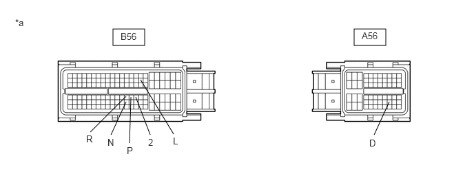
| *a | Front view of wire harness connector
(to ECM) |
- | - |
- Standard Voltage:
Tester Connection Condition Specified Condition B56 - 77 (P) - Body ground Shift lever in P 11 to 14 V Shift lever not in P Below 1 V B56 - 76 (R) - Body ground Shift lever in R 11 to 14 V Shift lever not in R Below 1 V B56 - 99 (N) - Body ground Shift lever in N 11 to 14 V Shift lever not in N Below 1 V A56 - 47 (D) - Body ground Shift lever in D or 3 11 to 14 V Shift lever not in D or 3 Below 1 V B56 - 78 (2) - Body ground Shift lever in 2 11 to 14 V Shift lever not in 2 Below 1 V B56 - 39 (L) - Body ground Shift lever in L 11 to 14 V Shift lever not in L Below 1 V
- Result:
Proceed to OK NG
OK
NG
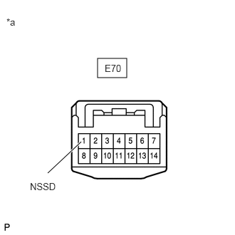
| *a | Front view of wire harness connector
(to Transmission Control Switch) |
Connect the park/neutral position switch assembly connector.
Disconnect the transmission control switch connector.
Turn the ignition switch to ON, and measure the voltage according to the value(s) in the table below when the shift lever is moved to each position.
- Standard Voltage:
Tester Connection Condition Specified Condition E70-1 (NSSD) - Body ground Shift lever in D or 3 11 to 14 V Shift lever not in D or 3 Below 1 V
- Result:
Proceed to OK NG
OK
NG
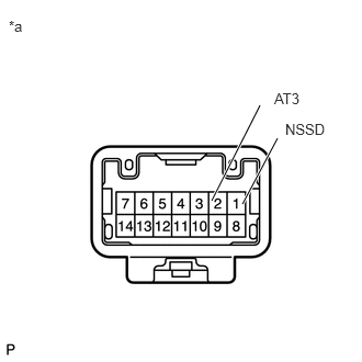
| *a | Component without harness connected
(Transmission Control Switch) |
Measure resistance according to the value(s) in the table below when the shift lever is moved to each position.
- Standard Resistance:
Tester Connection Condition Specified Condition 1 (NSSD) - 2 (AT3) Shift lever in 3 and 2 Below 1 Ω Shift lever not in 3 and 2 10 kΩ or higher
- Result:
Proceed to OK NG
OK
NG
Connect the transmission control switch connector.
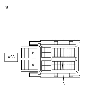
| *a | Front view of wire harness connector
(to ECM) |
Turn the ignition switch to ON, and measure the voltage according to the value(s) in the table below when the shift lever is moved to each position.
- Standard Voltage:
Tester Connection Condition Specified Condition A56-26 (3) - Body ground Shift lever in 3 11 to 14 V Shift lever not in 3 Below 1 V
- Result:
Proceed to OK NG
OK
NG
Disconnect the ECM connector.
Measure the resistance according to the value(s) in the table below.
- Standard Resistance:
Tester Connection Condition Specified Condition B14-4 (B) - A56-25 (NSW) Always Below 1 Ω
Measure the resistance according to the value(s) in the table below.
- Standard Resistance (Check for short):
Tester Connection Condition Specified Condition B14-4 (B) - Body ground Always 10 kΩ or higher A56-25 (NSW) - Body ground Always 10 kΩ or higher
- Result:
Proceed to OK NG
OK
NG