U441E AUTOMATIC TRANSMISSION / TRANSAXLE AUTOMATIC TRANSAXLE UNIT DISASSEMBLY
PROCEDURE

 35572A
1.REMOVE TRANSMISSION CONTROL SHAFT LEVER
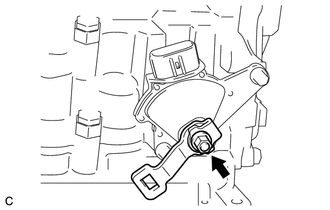
Remove the nut, washer and transmission control shaft lever from the manual valve lever shaft.

 84540
2.REMOVE PARK/NEUTRAL POSITION SWITCH
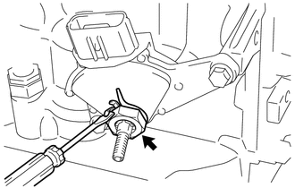
Using a screwdriver, pry back the tabs of the lock plate.
Remove the lock nut and lock plate from the park/neutral position switch assembly.
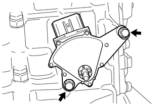
Remove the 2 bolts and park/neutral position switch assembly from the transaxle case.

 89413B
3.REMOVE TRANSMISSION REVOLUTION SENSOR
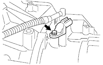
Remove the bolt and transmission revolution sensor from the transaxle case.
Remove the O-ring from the transmission revolution sensor.

 35104V
4.REMOVE BREATHER PLUG HOSE
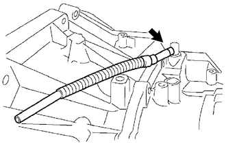
Remove the breather plug hose from the No. 1 breather plug.

 35104B
5.REMOVE NO. 1 BREATHER PLUG
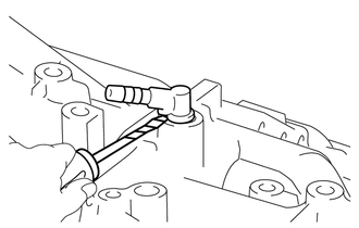
| *a | Protective Tape |
Using a screwdriver, remove the No. 1 breather plug from the transaxle case.
- HINT:
-
Tape the screwdriver tip before use.
Remove the O-ring from the No. 1 breather plug.

 32921C
6.REMOVE OIL COOLER TUBE UNION
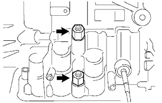
Remove the 2 oil cooler tube unions from the transaxle case.
Remove the 2 O-rings from the 2 oil cooler tube unions.

 30500
7.SECURE AUTOMATIC TRANSAXLE ASSEMBLY
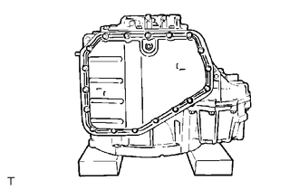
| *a | Wooden Block |
Place the automatic transaxle assembly on wooden blocks.

 35106D
8.REMOVE AUTOMATIC TRANSAXLE OIL PAN SUB-ASSEMBLY
Remove the drain plug sub-assembly and gasket from the automatic transaxle oil pan sub-assembly.
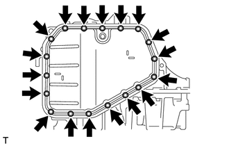
Remove the 18 bolts, automatic transaxle oil pan sub-assembly and automatic transaxle oil pan gasket from the transaxle case.

 35394
9.REMOVE TRANSMISSION OIL CLEANER MAGNET

 35330
10.REMOVE VALVE BODY OIL STRAINER ASSEMBLY

 35410
11.REMOVE TRANSMISSION VALVE BODY ASSEMBLY
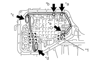
| *1 | Temperature Sensor Clamp |
| *a | Shift Solenoid Valve S1 Connector |
| *b | Shift Solenoid Valve S2 Connector |
| *c | Shift Solenoid Valve SLT Connector |
| *d | Shift Solenoid Valve SL Connector |
| *e | Shift Solenoid Valve ST Connector |
Disengage the temperature sensor clamp.
Disengage the 2 clamps.
Disconnect the shift solenoid valve S1 connector.
Disconnect the shift solenoid valve S2 connector.
Disconnect the shift solenoid valve SLT connector.
Disconnect the shift solenoid valve SL connector.
Disconnect the shift solenoid valve ST connector.
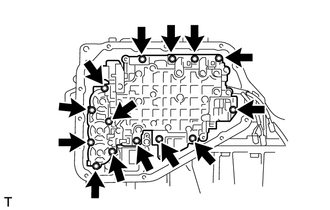
Remove the 14 bolts and separate the transmission valve body assembly from the transaxle case.
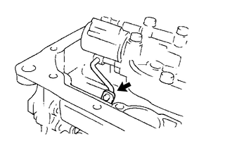
Disconnect the manual valve connecting rod from the manual valve lever sub-assembly to remove the transmission valve body assembly from the transaxle case.

 82125J
12.REMOVE TRANSMISSION WIRE
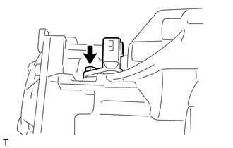
Remove the bolt.
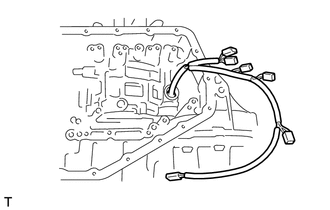
Pull out the transmission wire from the transaxle case.
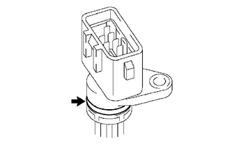
Remove the O-ring from the transmission wire.

 35148
13.REMOVE NO. 1 GOVERNOR APPLY GASKET
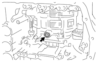
Remove the No. 1 governor apply gasket from the transaxle case.

 35159
14.REMOVE BRAKE DRUM GASKET
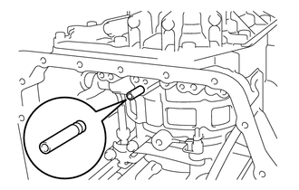
Remove the brake drum gasket from the transaxle case.

 35251
15.REMOVE CHECK BALL BODY
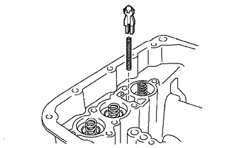
Remove the check ball body and check ball body compression spring from the transaxle case.

 35425A
16.REMOVE C-2 ACCUMULATOR PISTON
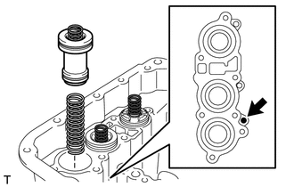
Apply compressed air (392 kPa (4.0 kgf/cm2, 57 psi)) to the oil hole and remove the C-2 accumulator piston and C-2 accumulator piston compression spring.
- NOTICE:
- ·
Applying compressed air may cause the C-2 accumulator piston to jump out. When removing the C-2 accumulator piston, hold it by hand using a piece of cloth.
·Be careful when applying compressed air as ATF may spray out.
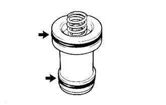
Remove the 2 C-2 accumulator piston O-rings from the C-2 accumulator piston.

 35209
17.REMOVE C-2 ACCUMULATOR SPRING SUB-ASSEMBLY
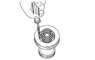
| *a | Protective Tape |
Using a screwdriver, remove the accumulator spring hole snap ring and C-2 accumulator spring sub-assembly from the C-2 accumulator piston.
- HINT:
-
Tape the screwdriver tip before use.

 35424C
18.REMOVE C-1 ACCUMULATOR PISTON
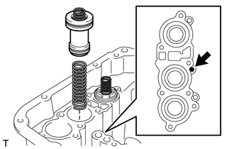
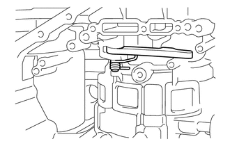
Apply compressed air (392 kPa (4.0 kgf/cm2, 57 psi)) to the oil hole and remove the C-1 accumulator piston and C-1 accumulator piston compression spring.
- NOTICE:
- ·
Applying compressed air may cause the C-1 accumulator piston to jump out. When removing the C-1 accumulator piston, hold it with your hand using a piece of cloth.
·Be careful when applying compressed air as ATF may spray out.
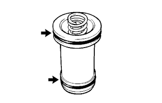
Remove the 2 C-1 accumulator piston O-rings from the C-1 accumulator piston.

 35206
19.REMOVE C-1 ACCUMULATOR SPRING SUB-ASSEMBLY
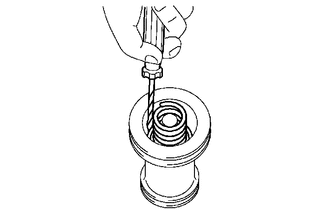
| *a | Protective Tape |
Using a screwdriver, remove the C-1 accumulator spring sub-assembly from the C-1 accumulator piston.
- HINT:
-
Tape the screwdriver tip before use.

 35427R
20.REMOVE B-1 ACCUMULATOR PISTON
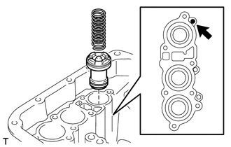
Remove the No. 2 B-1 accumulator piston compression spring from the B-1 accumulator piston.
Apply compressed air (392 kPa (4.0 kgf/cm2, 57 psi)) to the oil hole and remove the B-1 accumulator piston.
- NOTICE:
- ·
Applying compressed air may cause the B-1 accumulator piston to jump out. When removing the B-1 accumulator piston, hold it with your hand using a piece of cloth.
·Be careful when applying compressed air as ATF may spray out.
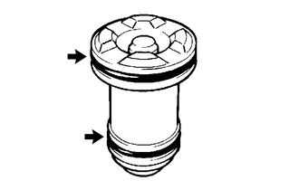
Remove the 2 B-1 accumulator piston O-rings from the B-1 accumulator piston.

 35427P
21.REMOVE B-1 ACCUMULATOR PISTON COMPRESSION SPRING
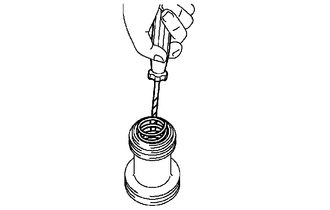
| *a | Protective Tape |
Using a screwdriver, remove the B-1 accumulator piston compression spring from the B-1 accumulator piston.
- HINT:
-
Tape the screwdriver tip before use.

 35111C
22.REMOVE TRANSAXLE HOUSING
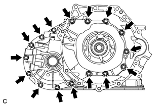
Remove the 16 bolts.
Tap around the circumference of the transaxle housing with a plastic hammer and remove the transaxle housing from the transaxle case.
- NOTICE:
-
The differential gear assembly may be accidentally removed when the transaxle housing is removed.

 35148A
23.REMOVE NO. 2 GOVERNOR APPLY GASKET
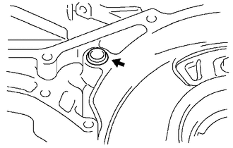
Remove the No. 2 governor apply gasket from the transaxle case.

 24.INSPECT INPUT SHAFT SUB-ASSEMBLY END PLAY

 25.REMOVE OIL PUMP ASSEMBLY
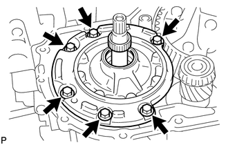
Remove the 6 bolts and oil pump assembly from the transaxle case.

 35701
26.REMOVE INPUT SHAFT SUB-ASSEMBLY
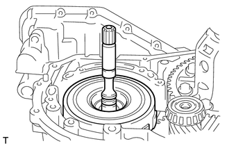
Remove the input shaft sub-assembly from the transaxle case.

 35370A
27.REMOVE STATOR SHAFT THRUST NEEDLE ROLLER BEARING
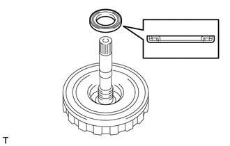
Remove the stator shaft thrust needle roller bearing from the input shaft sub-assembly.

 35667A
28.REMOVE DIRECT CLUTCH DISC
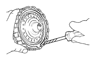
| *a | Protective Tape |
Using a screwdriver, remove the direct clutch flange hole snap ring from the input shaft sub-assembly.
- HINT:
-
Tape the screwdriver tip before use.
Remove the direct clutch flange, 2 direct clutch discs and 2 direct clutch clutch plates from the input shaft sub-assembly.

 35604
29.REMOVE DIRECT CLUTCH RETURN SPRING SUB-ASSEMBLY
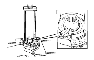
Using SST, a press and a snap ring expander, remove the direct clutch return spring snap ring from the input shaft sub-assembly.
- SST
- 09387-00020
Remove the direct clutch return spring sub-assembly from the input shaft sub-assembly.

 35606A
30.REMOVE DIRECT CLUTCH PISTON SUB-ASSEMBLY
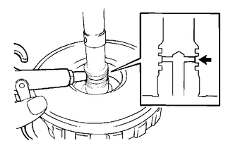
Apply compressed air (392 kPa (4.0 kgf/cm2, 57 psi)) to the input shaft sub-assembly to remove the direct clutch piston sub-assembly from the input shaft sub-assembly.
- NOTICE:
- ·
Applying compressed air may cause the direct clutch piston sub-assembly to jump out. When removing the direct clutch piston sub-assembly, hold it by hand using a piece of cloth.
·Be careful when applying compressed air as ATF may spray out.

 35606C
31.REMOVE DIRECT CLUTCH PISTON O-RING
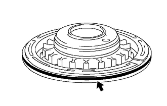
Remove the direct clutch piston O-ring from the direct clutch piston sub-assembly.
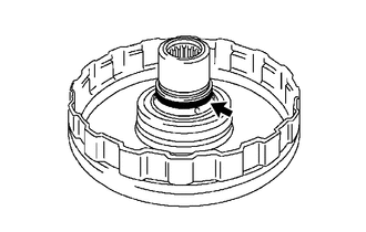
Remove the direct clutch piston O-ring from the input shaft sub-assembly.

 35712A
32.REMOVE INPUT SHAFT OIL SEAL RING
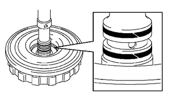
Remove the 2 input shaft oil seal rings from the input shaft sub-assembly.

 35720J
33.REMOVE PLANETARY GEAR FRONT THRUST NEEDLE ROLLER BEARING
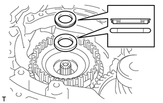
| *1 | Planetary Gear Front Thrust Needle Roller Bearing |
| *2 | Planetary Gear Thrust Bearing Race |
Remove the planetary gear front thrust needle roller bearing and planetary gear thrust bearing race from the transaxle case.

 35654B
34.REMOVE DIRECT CLUTCH HUB
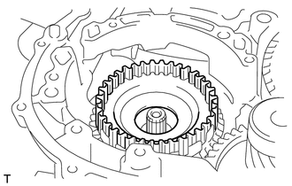
Remove the direct clutch hub from the transaxle case.

 35.REMOVE DIFFERENTIAL GEAR ASSEMBLY
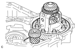
Remove the differential gear assembly and differential drive pinion with counter driven gear from the transaxle case.

 35102
36.REMOVE TRANSAXLE REAR COVER SUB-ASSEMBLY
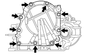
Remove the 9 bolts.
Tap around the circumference of the transaxle rear cover sub-assembly with a plastic hammer and remove the transaxle rear cover sub-assembly from the transaxle case.

 34603B
37.REMOVE OVERDRIVE BRAKE RETURN SPRING SUB-ASSEMBLY
| *a | Protective Tape |
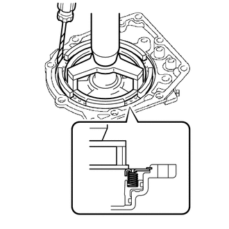
Using SST, a press and a screwdriver, remove the overdrive brake return spring hole snap ring from the transaxle rear cover sub-assembly.
- SST
- 09387-00070
- HINT:
-
Tape the screwdriver tip before use.
Remove the overdrive brake return spring sub-assembly from the transaxle rear cover sub-assembly.

 34622B
38.REMOVE 2ND COAST AND OVERDRIVE BRAKE PISTON
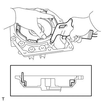
Apply compressed air (392 kPa (4.0 kgf/cm2, 57 psi)) to the transaxle rear cover sub-assembly to remove the 2nd coast and overdrive brake piston from the transaxle rear cover sub-assembly.
- NOTICE:
- ·
Applying compressed air may cause the 2nd coast and overdrive brake piston to jump out. When removing the 2nd coast and overdrive brake piston, hold it by hand using a piece of cloth.
·Be careful when applying compressed air as ATF may spray out.

 34622C
39.REMOVE 2ND COAST AND OVERDRIVE O-RING
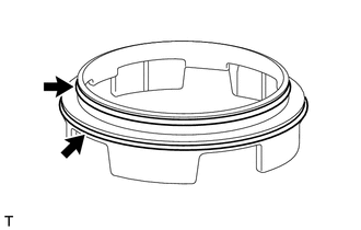
Remove the 2 2nd coast and overdrive O-rings from the 2nd coast and overdrive brake piston.

 35617G
40.REMOVE CLUTCH DRUM OIL SEAL RING
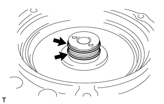
Remove the 2 clutch drum oil seal rings from the transaxle rear cover sub-assembly.

 35102B
41.REMOVE TRANSAXLE REAR COVER PLUG
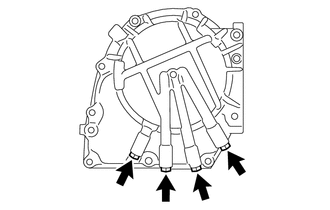
Remove the 4 transaxle rear cover plugs from the transaxle rear cover sub-assembly.
Remove the 4 O-rings from the 4 transaxle rear cover plugs.

 35149B
42.REMOVE TRANSAXLE CASE 2ND BRAKE GASKET
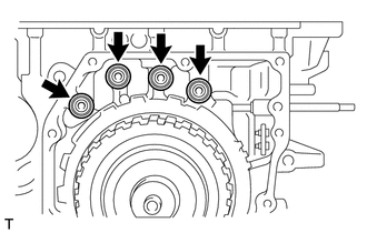
Remove the 4 transaxle case 2nd brake gaskets from the transaxle case.

 35601D
43.REMOVE FRONT CLUTCH DRUM THRUST NEEDLE ROLLER BEARING
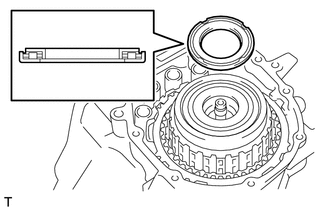
Remove the front clutch drum thrust needle roller bearing from the intermediate shaft sub-assembly.

 35708G
44.REMOVE INTERMEDIATE SHAFT SUB-ASSEMBLY
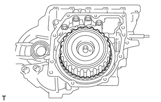
Remove the intermediate shaft sub-assembly from the transaxle case.

 35706G
45.REMOVE SUN GEAR REAR THRUST BEARING
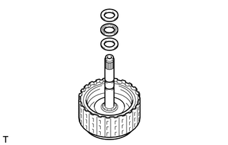
| *1 | Front Planetary Flange Rear Thrust Bearing Race |
| *2 | Sun Gear Rear Thrust Bearing |
| *3 | Sun Gear Rear Thrust Bearing Race |
Remove the front planetary flange rear thrust bearing race, sun gear rear thrust bearing and sun gear rear thrust bearing race from the intermediate shaft sub-assembly.

 35677H
46.REMOVE REVERSE CLUTCH DISC
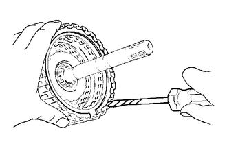
| *a | Protective Tape |
Using a screwdriver, remove the reverse clutch flange hole snap ring from the intermediate shaft sub-assembly.
- HINT:
-
Tape the screwdriver tip before use.
Remove the 2 reverse clutch flanges, 2 reverse clutch discs and No. 3 clutch plate from the intermediate shaft sub-assembly.

 35633
47.REMOVE FRONT CLUTCH CLUTCH DISC
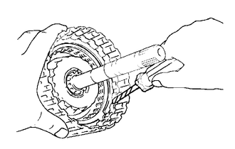
| *a | Protective Tape |
Using a screwdriver, remove the forward clutch flange hole snap ring from the clutch drum sub-assembly.
- HINT:
-
Tape the screwdriver tip before use.
Remove the forward clutch flange, 4 front clutch clutch discs and 4 forward clutch clutch plates from the clutch drum sub-assembly.

 35668
48.REMOVE NO. 1 CLUTCH BALANCER
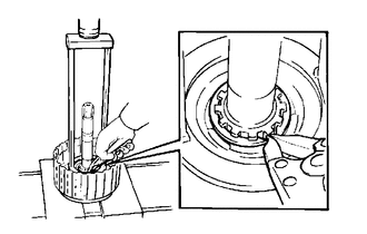
Using SST, a press and a snap ring expander, remove the clutch balancer snap ring from the intermediate shaft sub-assembly.
- SST
- 09387-00020
Remove the No. 1 clutch balancer from the intermediate shaft sub-assembly.

 35603A
49.REMOVE FORWARD CLUTCH RETURN SPRING SUB-ASSEMBLY
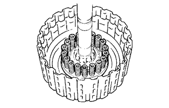
Remove the forward clutch return spring sub-assembly from the intermediate shaft sub-assembly.

 35612B
50.REMOVE FORWARD CLUTCH PISTON
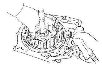
Install the intermediate shaft sub-assembly to the transaxle rear cover sub-assembly.
Apply compressed air (392 kPa (4.0 kgf/cm2, 57 psi)) to the transaxle rear cover sub-assembly to remove the forward clutch piston from the intermediate shaft sub-assembly.
- NOTICE:
- ·
Applying compressed air may cause the forward clutch piston to jump out. When removing the forward clutch piston, hold it by hand using a piece of cloth.
·Be careful when applying compressed air as ATF may spray out.

 35601
51.REMOVE CLUTCH DRUM SUB-ASSEMBLY
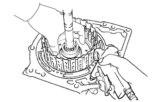
Install the intermediate shaft sub-assembly to the transaxle rear cover sub-assembly.
Apply compressed air (392 kPa (4.0 kgf/cm2, 57 psi)) to the transaxle rear cover sub-assembly to remove the clutch drum sub-assembly from the intermediate shaft sub-assembly.
- NOTICE:
- ·
Applying compressed air may cause the clutch drum sub-assembly to jump out. When removing the clutch drum sub-assembly, hold it by hand using a piece of cloth.
·Be careful when applying compressed air as ATF may spray out.

 35612C
52.REMOVE FORWARD CLUTCH PISTON O-RING
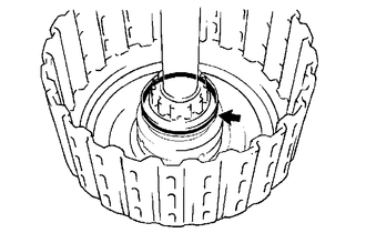
Remove the forward clutch piston O-ring from the intermediate shaft sub-assembly.

 35601B
53.REMOVE FRONT CLUTCH DRUM O-RING
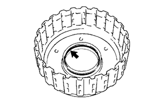
Remove the front clutch drum O-ring from the clutch drum sub-assembly.

 35748C
54.REMOVE INTERMEDIATE SHAFT OIL SEAL RING
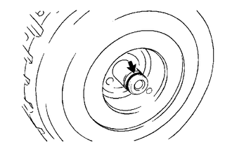
Remove the intermediate shaft oil seal ring from the intermediate shaft sub-assembly.

 34633
55.REMOVE 2ND COAST AND OVERDRIVE BRAKE DISC
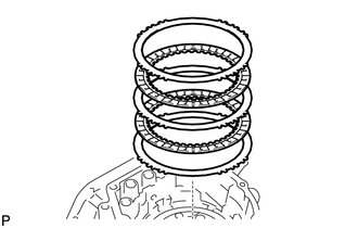
| *1 | 2nd Coast And Overdrive Brake Flange |
| *2 | 2nd Coast And Overdrive Brake Disc |
| *3 | 2nd Coast And Overdrive Brake Plate |
| *4 | No. 2 2nd Coast And Overdrive Brake Flange |
Remove the 2nd coast and overdrive brake flange, 2 2nd coast and overdrive brake discs, 2nd coast and overdrive brake plate and No. 2 2nd coast and overdrive brake flange from the transaxle case.

 34625E
56.REMOVE 2ND COAST AND OVERDRIVE BRAKE FLANGE HOLE SNAP RING
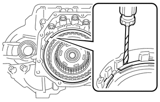
| *a | Protective Tape |
Using a screwdriver, remove the 2nd coast and overdrive brake flange hole snap ring from the transaxle case.
- HINT:
-
Tape the screwdriver tip before use.

 35061
57.REMOVE FORWARD CLUTCH HUB SUB-ASSEMBLY
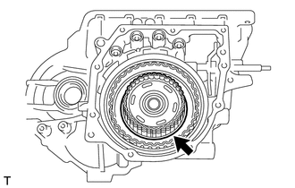
Remove the forward clutch hub sub-assembly from the transaxle case.

 35061C
58.REMOVE FORWARD CLUTCH HUB THRUST NEEDLE ROLLER BEARING
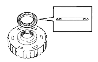
Remove the forward clutch hub thrust needle roller bearing from the forward clutch hub sub-assembly.

 35061B
59.REMOVE FORWARD CLUTCH HUB THRUST BEARING RACE
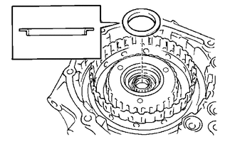
Remove the forward clutch hub thrust bearing race from the rear planetary sun gear assembly.

 35730
60.REMOVE REAR PLANETARY SUN GEAR ASSEMBLY
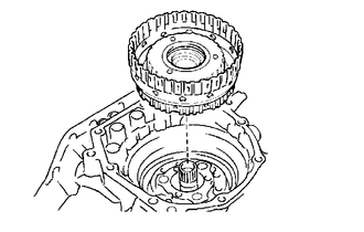
Remove the rear planetary sun gear assembly with one-way clutch assembly from the transaxle case.

 35720K
61.REMOVE PLANETARY GEAR REAR THRUST NEEDLE ROLLER BEARING
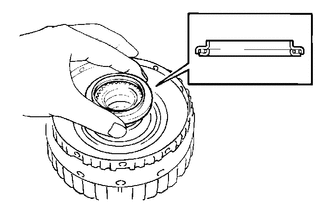
Remove the planetary gear rear thrust needle roller bearing from the rear planetary sun gear assembly.

 35790A
62.INSPECT ONE-WAY CLUTCH ASSEMBLY

 35790A
63.REMOVE ONE-WAY CLUTCH ASSEMBLY
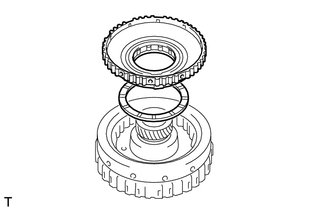
| *1 | One-way Clutch Assembly |
| *2 | No. 2 Planetary Carrier Thrust Washer |
Remove the one-way clutch assembly and No. 2 planetary carrier thrust washer from the rear planetary sun gear assembly.

 35737
64.REMOVE PLANETARY CARRIER THRUST WASHER
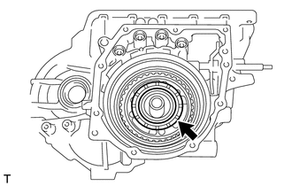
Remove the planetary carrier thrust washer from the transaxle case.

 35706
65.REMOVE PLANETARY SUN GEAR SUB-ASSEMBLY
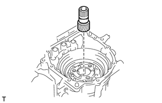
Remove the planetary sun gear sub-assembly from the transaxle case.

 35789
66.REMOVE FRONT PLANETARY FLANGE FRONT THRUST BEARING RACE
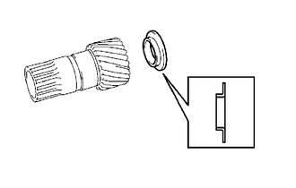
Remove the front planetary flange front thrust bearing race from the planetary sun gear sub-assembly.

 35664C
67.REMOVE 2ND BRAKE CYLINDER
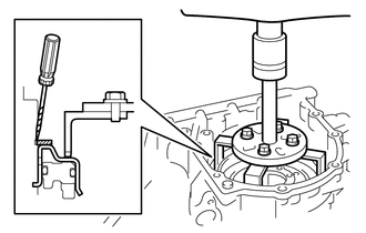
| *1 | 2nd Brake Cylinder Hole Snap Ring |
| *2 | 2nd Brake Cylinder |
| *a | Protective Tape |
Using SST, a press and a screwdriver, remove the 2nd brake cylinder hole snap ring from the transaxle case.
- SST
- 09387-00100
09950-70010 (09951-07100)
- HINT:
-
Tape the screwdriver tip before use.
Remove the 2nd brake cylinder from the transaxle case.

 35624E
68.REMOVE 2ND BRAKE PISTON
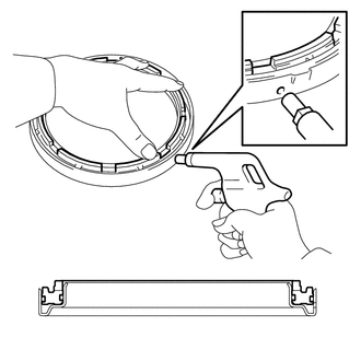
Apply compressed air (392 kPa (4.0 kgf/cm2, 57 psi)) to the 2nd brake cylinder to remove the 2nd brake piston from the 2nd brake cylinder.
- NOTICE:
- ·
Applying compressed air may cause the 2nd brake piston to jump out. When removing the 2nd brake piston, hold it by hand using a piece of cloth.
·Be careful when applying compressed air as ATF may spray out.

 35664D
69.REMOVE 2ND BRAKE CYLINDER O-RING
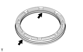
Remove the 2 2nd brake cylinder O-rings from the 2nd brake piston.

 35608L
70.REMOVE 2ND BRAKE PISTON RETURN SPRING SUB-ASSEMBLY
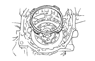
Remove the 2nd brake piston return spring sub-assembly from the transaxle case.

 35682
71.REMOVE 2ND BRAKE BRAKE DISC
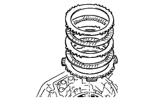
| *1 | 2nd Brake Brake Plate |
| *2 | 2nd Brake Brake Disc |
| *3 | 2nd Brake Brake Flange |
Remove the 2 2nd brake brake plates, 2 2nd brake brake discs and 2nd brake brake flange from the transaxle case.

 34365A
72.REMOVE OUTER RACE RETAINER
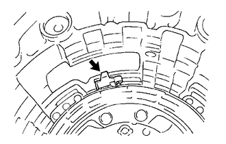
Remove the outer race retainer from the transaxle case.

 35792C
73.INSPECT NO. 2 ONE-WAY CLUTCH

 35792C
74.REMOVE NO. 2 ONE-WAY CLUTCH
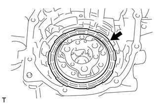
Remove the No. 2 one-way clutch from the transaxle case.

 35720G
75.REMOVE PLANETARY GEAR ASSEMBLY
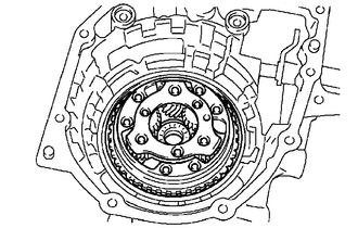
Remove the planetary gear assembly from the transaxle case.

 35683
76.REMOVE 1ST AND REVERSE BRAKE DISC
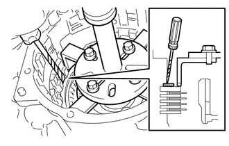
| *a | Protective Tape |
Using SST, a press and a screwdriver, remove the brake flange hole snap ring from the transaxle case.
- SST
- 09387-00100
09950-70010 (09951-07100)
- HINT:
-
Tape the screwdriver tip before use.
Remove the 1st and reverse brake flange, 4 1st and reverse brake discs and 4 1st and reverse brake plates from the transaxle case.

 35068
77.REMOVE 1ST AND REVERSE BRAKE RETURN SPRING SUB-ASSEMBLY
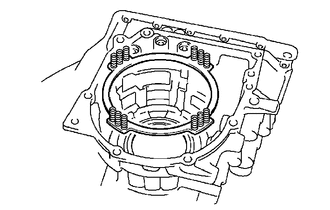
Remove the 1st and reverse brake return spring sub-assembly from the transaxle case.

 35782H
78.REMOVE COUNTER DRIVE GEAR NUT
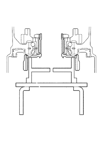
Using SST, support the transaxle case.
- SST
- 09223-15020
09387-00060
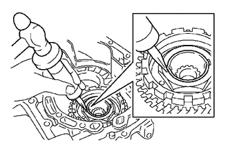
Using SST and a hammer, release the staked part of the planetary ring gear flange.
- SST
- 09930-00010
- NOTICE:
-
If a chisel or other tool is used to unstake the planetary ring gear flange, the impact may damage the bearing.
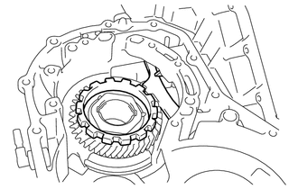
| *1 | Counter Drive Gear |
| *2 | Parking Lock Pawl |
Secure the counter drive gear with the parking lock pawl.
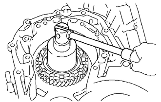
Using a 55 mm socket wrench, remove the counter drive gear nut from the planetary ring gear flange.

 35743K
79.REMOVE PLANETARY RING GEAR
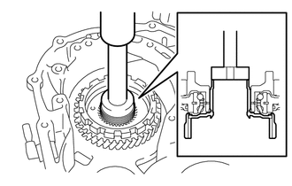
Using SST and a press, remove the planetary ring gear from the transaxle case.
- SST
- 09950-60010 (09951-00420)
09950-70010 (09951-07100)

 35762E
80.REMOVE PLANETARY RING GEAR FLANGE
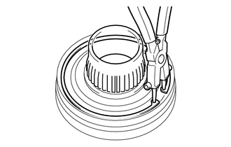
Using snap ring pliers, remove the planetary ring gear hole snap ring from the planetary ring gear.
Remove the planetary ring gear flange from the planetary ring gear.

 35782C
81.REMOVE COUNTER DRIVE GEAR
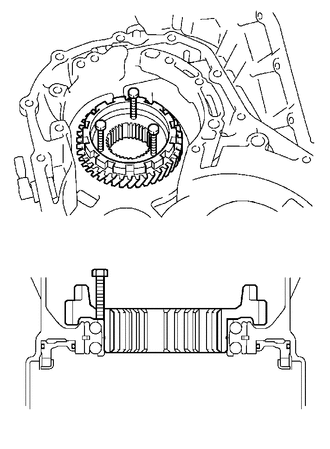
Install 3 service bolts to the counter drive gear.
| Diameter | Pitch | Length |
|---|---|---|
| 6 mm (0.236 in.) | 1.0 mm (0.0394 in.) | 40 to 80 mm (1.58 to 3.14 in.) |
Tighten the 3 service bolts to remove the counter drive gear from the transaxle case.

 35623H
82.REMOVE 1ST AND REVERSE BRAKE PISTON
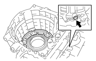
Apply compressed air (392 kPa (4.0 kgf/cm2, 57 psi)) to the transaxle case to remove the 1st and reverse brake piston from the transaxle case.
- NOTICE:
- ·
Applying compressed air may cause the 1st and reverse brake piston to jump out. When removing the 1st and reverse brake piston, hold it by hand using a piece of cloth.
·Be careful when applying compressed air as ATF may spray out.

 35623J
83.REMOVE 1ST AND REVERSE BRAKE O-RING
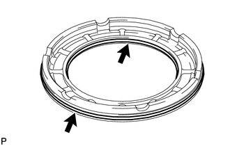
Remove the 2 1st and reverse brake O-rings from the 1st and reverse brake piston.

 35595
84.REMOVE PARKING LOCK PAWL BRACKET
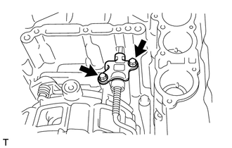
Remove the 2 bolts and parking lock pawl bracket from the transaxle case.

 35561
85.REMOVE MANUAL VALVE LEVER SHAFT
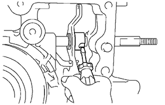
Using a screwdriver, cut off the manual valve lever shaft spacer and remove it from the manual valve lever sub-assembly.
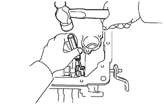
Using a 3 mm pin punch and a hammer, remove the slotted spring pin from the manual valve lever sub-assembly.
Remove the manual valve lever shaft and manual valve lever sub-assembly from the transaxle case.

 35501
86.REMOVE PARKING LOCK ROD SUB-ASSEMBLY
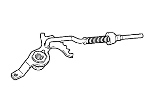
Remove the parking lock rod sub-assembly from the manual valve lever sub-assembly.

 35506F
87.REMOVE MANUAL VALVE LEVER SHAFT OIL SEAL
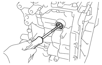
| *a | Protective Tape |
Using a screwdriver with its tip wrapped with protective tape, pry out the manual valve lever shaft oil seal from the transaxle case.

 35409D
88.REMOVE MANUAL DETENT SPRING SUB-ASSEMBLY
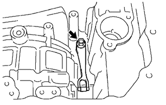
Remove the bolt and manual detent spring sub-assembly from the transaxle case.

 35557
89.REMOVE PARKING LOCK PAWL
| *1 | Parking Lock Pawl Shaft |
| *2 | Parking Lock Pawl Torsion Spring |
| *3 | Parking Lock Pawl |
Remove the parking lock pawl shaft, parking lock pawl torsion spring and parking lock pawl from the transaxle case.

 35165
90.REMOVE NO. 1 TRANSMISSION CASE PLATE
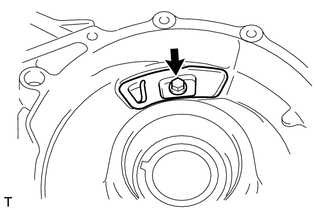
Remove the bolt and No. 1 transmission case plate from the transaxle case.

 35174
91.REMOVE TRANSAXLE HOUSING OIL SEPARATOR
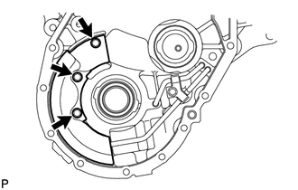
Remove the 3 bolts and transaxle housing oil separator from the transaxle housing.

 35195A
92.REMOVE NO. 1 TRANSAXLE APPLY TUBE CLAMP
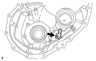
Remove the bolt and No. 1 transaxle apply tube clamp from the transaxle housing.

 35847
93.REMOVE TRANSMISSION LUBE APPLY TUBE
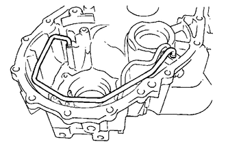
Remove the transmission lube apply tube from the transaxle housing.
- NOTICE:
-
Do not apply excessive force to the transmission lube apply tube.

 35882A
94.REMOVE DIFFERENTIAL GEAR LUBE APPLY TUBE
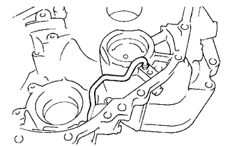
Remove the differential gear lube apply tube from the transaxle housing.
- NOTICE:
-
Do not apply excessive force to the differential gear lube apply tube.

 43420H
95.REMOVE FRONT DRIVE SHAFT OIL SEAL LH
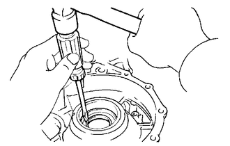
Using a screwdriver and a hammer, remove the front drive shaft oil seal LH from the transaxle case.

 43410M
96.REMOVE FRONT DRIVE SHAFT OIL SEAL RH
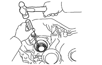
Using a screwdriver and a hammer, remove the front drive shaft oil seal RH from the transaxle housing.

 35104Q
97.REMOVE NO. 1 TRANSAXLE CASE PLUG
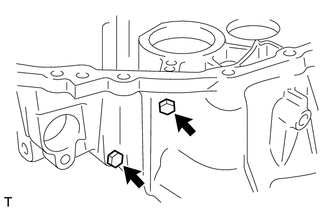
Remove the 2 No. 1 transaxle case plugs from the transaxle housing.
Remove the 2 O-rings from the 2 No. 1 transaxle case plugs.

 35104R
98.REMOVE NO. 2 TRANSAXLE CASE PLUG
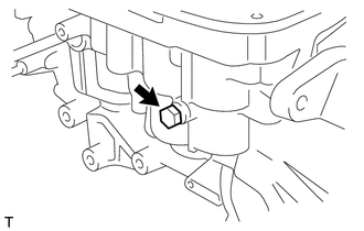
Remove the No. 2 transaxle case plug from the transaxle case.
Remove the O-ring from the No. 2 transaxle case plug.

 41211B
99.REMOVE FRONT DRIVE PINION REAR TAPERED ROLLER BEARING
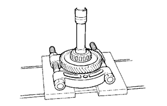
Using SST and a press, remove the front drive pinion rear tapered roller bearing (inner race) and counter driven gear from the differential drive pinion.
- SST
- 09950-00020
09950-60010 (09951-00280)
09950-70010 (09951-07100)
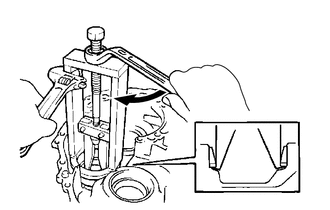
| *a | Hold |
| *b | Turn |
Using SST, remove the front drive pinion rear tapered roller bearing (outer race) and drive pinion rear plate washer from the transaxle case.
- SST
- 09387-00041 (09387-01030, 09387-01041)
09387-02010
09387-02020
- NOTICE:
-
Apply a small amount of grease to the threads of SST before use.

 41211A
100.REMOVE FRONT DRIVE PINION FRONT TAPERED ROLLER BEARING
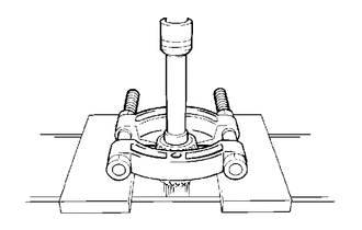
Using SST and a press, remove the front drive pinion front tapered roller bearing (inner race) from the differential drive pinion.
- SST
- 09950-00020
09950-60010 (09951-00280)
09950-70010 (09951-07100)
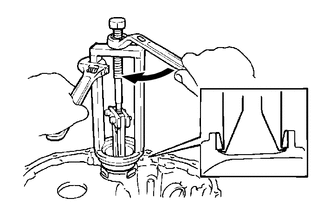
| *a | Hold |
| *b | Turn |
Using SST, remove the front drive pinion front tapered roller bearing (outer race) from the transaxle housing.
- SST
- 09316-20011
09387-00041 (09387-01030, 09387-01041)
09387-02020
- NOTICE:
-
Apply a small amount of grease to the threads of SST before use.

 41211E
101.REMOVE DIFFERENTIAL DRIVE PINION PLUG
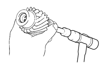
Using an extension bar and a plastic hammer, remove the differential drive pinion plug from the differential drive pinion.