2ZR-FE ENGINE MECHANICAL ENGINE UNIT INSPECTION
PROCEDURE

 13801
1.INSPECT NO. 1 VALVE ROCKER ARM SUB-ASSEMBLY
13801
1.INSPECT NO. 1 VALVE ROCKER ARM SUB-ASSEMBLY
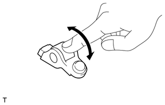
Turn the roller by hand to check that it turns smoothly.
- HINT:
-
If the roller does not turn smoothly, replace the No. 1 valve rocker arm sub-assembly.
13750
2.INSPECT VALVE LASH ADJUSTER ASSEMBLY
- NOTICE:
- ·
Keep the valve lash adjuster assembly free of dirt and foreign matter.
·Only use clean engine oil.
Place the valve lash adjuster assembly into a container filled with engine oil.
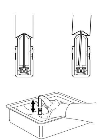
| *a | Correct |
| *b | Incorrect |
| *c | Taper Part |
| *d | Low Pressure Chamber |
| *e | High Pressure Chamber |
| *f | Plunger |
| *g | Check Ball |
Insert the SST tip into the valve lash adjuster plunger and use the tip to press down on the check ball inside the plunger.
- SST
- 09276-75010
Squeeze SST and the valve lash adjuster assembly together to move the plunger up and down 5 to 6 times.
Check the movement of the plunger and bleed it.
- OK:
Plunger moves up and down.
- NOTICE:
-
When bleeding the high-pressure chamber, make sure that the tip of SST is actually pressing the check ball as shown in the illustration. If the check ball is not pressed, the high-pressure chamber will not be bled.
After bleeding, remove SST. Then try to quickly and firmly press the plunger with a finger.
- OK:
Plunger is very difficult to move.
If the result is not as specified, replace the valve lash adjuster assembly.
13050
3.INSPECT CAMSHAFT TIMING GEAR ASSEMBLY
Install the camshaft timing gear assembly.
Click hereEngine / Hybrid System>2ZR-FE ENGINE MECHANICAL>CAMSHAFT>INSTALLATION
Check the lock of the camshaft timing gear assembly.
Confirm that the camshaft timing gear assembly is locked.
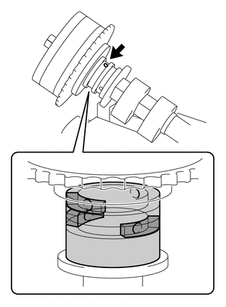
| *a | Open |
| *b | Close |
| *c | Advance Side Path |
| *d | Vinyl Tape |
| *e | Rubber Piece |
Release the lock pin.
Cover the 4 oil paths of the cam journal with vinyl tape as shown in the illustration.
- HINT:
-
There are 4 oil paths in the groove of the camshaft. Plug 3 of the paths with rubber pieces.
Prick a hole in the tape placed on the advance side path.
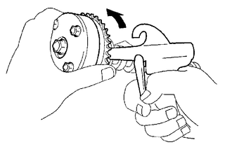
While applying approximately 150 kPa (1.5 kgf/cm2, 22 psi) of air pressure to the oil path, forcibly turn the camshaft timing gear assembly in the advance direction (counterclockwise).
- CAUTION:
-
Cover the path with a piece of cloth when applying pressure to keep oil from spraying.
- NOTICE:
-
Do not lock the camshaft timing gear assembly. If it is locked, release the lock pin again.
- HINT:
- ·
Depending on the air pressure applied, the camshaft timing gear assembly may be turned in the advance direction without applying any force.
·If enough air pressure cannot be applied because of air leakage from the port, releasing the lock pin may be difficult.
Check for smooth rotation.
Turn the camshaft timing gear assembly within its movable range (20.5 to 22.5°) 2 or 3 times, but do not turn it to the most retarded position. Make sure that the camshaft timing gear assembly turns smoothly.
- NOTICE:
-
Do not lock the camshaft timing gear assembly. If it is locked, release the lock pin again.
13070A
4.INSPECT CAMSHAFT TIMING EXHAUST GEAR ASSEMBLY
Install the camshaft timing exhaust gear assembly.
Click hereEngine / Hybrid System>2ZR-FE ENGINE MECHANICAL>CAMSHAFT>INSTALLATION
Check the lock of the camshaft timing exhaust gear assembly.
Make sure that the camshaft timing exhaust gear assembly is locked.
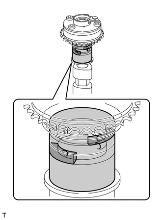
| *a | Open |
| *b | Close |
| *c | Advance Side Path |
| *d | Retard Side Path |
| *e | Vinyl Tape |
| *f | Rubber Piece |
Release the lock pin.
Cover the 4 oil paths of the cam journal with vinyl tape as shown in the illustration.
- HINT:
-
There are 4 oil paths in the groove of the camshaft. Plug 2 of the paths with rubber pieces.
Prick a hole in the tape placed on the advance side path. Prick a hole in the tape placed on the retard side path, on the opposite side to that of the advance side path, as shown in the illustration.
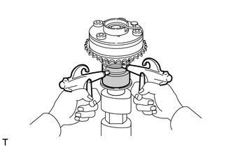
| *a | Advance Side Path |
| *b | Retard Side Path |
Apply approximately 200 kPa (2.0 kgf/cm2, 29 psi) of air pressure to the 2 open paths (the advance side path and the retard side path).
- CAUTION:
-
Cover the paths with a piece of cloth when applying pressure to keep oil from spraying.
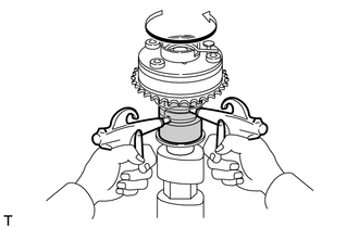
| *a | Decompress |
| *b | Hold Pressure |
| *c | Advance Side Path |
| *d | Retard Side Path |
Make sure that the camshaft timing exhaust gear assembly turns in the retard direction when reducing the air pressure applied to the advance side path.
- HINT:
-
The lock pin is released and the camshaft timing exhaust gear assembly turns in the retard direction.
When the camshaft timing exhaust gear assembly moves to the most retarded position, release the air pressure from the advance side path, and then release the air pressure from the retard side path.
- NOTICE:
-
Be sure to release the air pressure from the advance side path first. If the air pressure of the retard side path is released first, the camshaft timing exhaust gear assembly may abruptly shift in the advance direction and break the lock pin or other parts.
Check for smooth rotation.
Turn the camshaft timing exhaust gear assembly within its movable range (19 to 21°) 2 or 3 times, but do not turn it to the most advanced position. Make sure that the camshaft timing exhaust gear assembly turns smoothly.
- NOTICE:
-
When the air pressure is released from the advance side path and then from the retard side path, the camshaft timing exhaust gear assembly automatically returns to the most advanced position due to the advance assist spring operation and locks. Gradually release the air pressure from the retard side path before performing the smooth rotation check.
Check the lock at the most advanced position.
Make sure that the camshaft timing exhaust gear assembly is locked at the most advanced position.
13506
5.INSPECT CHAIN SUB-ASSEMBLY
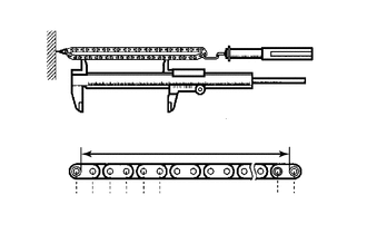
| *a | Measurement Length |
Using a spring scale, pull the chain sub-assembly with a force of 147 N (15 kgf, 33 lbf) as shown in the illustration.
Using a vernier caliper, measure the length of 15 links.
- Maximum Chain Elongation:
115.2 mm (4.54 in.)
- NOTICE:
-
Perform the measurement at 3 random places. Use the average of the measurements.
If the average elongation is greater than the maximum, replace the chain sub-assembly.
13507
6.INSPECT NO. 2 CHAIN SUB-ASSEMBLY
| *a | Measurement Length |
Using a spring scale, pull the No. 2 chain sub-assembly with a force of 147 N (15 kgf, 33 lbf) as shown in the illustration.
Using a vernier caliper, measure the length of 15 links.
- Maximum Chain Elongation:
102.1 mm (4.02 in.)
- NOTICE:
-
Perform the measurement at 3 random places. Use the average of the measurements.
If the average elongation is greater than the maximum, replace the No. 2 chain sub-assembly.
13519
7.INSPECT OIL PUMP DRIVE GEAR
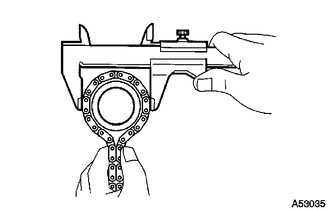
Place the No. 2 chain sub-assembly around the oil pump drive gear.
Using a vernier caliper, measure the diameter of the oil pump drive gear and No. 2 chain sub-assembly.
- Minimum Gear Diameter (with Chain):
48.2 mm (1.90 in.)
- NOTICE:
-
The vernier caliper must be in contact with the chain rollers when measuring.
If the diameter is less than the minimum, replace the No. 2 chain sub-assembly and oil pump drive gear.
15163
8.INSPECT OIL PUMP DRIVE SHAFT GEAR
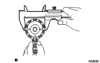
Place the No. 2 chain sub-assembly around the oil pump drive shaft gear.
Using a vernier caliper, measure the diameter of the oil pump drive shaft gear and No. 2 chain sub-assembly.
- Minimum Gear Diameter (with Chain):
48.2 mm (1.90 in.)
- NOTICE:
-
The vernier caliper must be in contact with the chain rollers when measuring.
If the diameter is less than the minimum, replace the No. 2 chain sub-assembly and oil pump drive shaft gear.
13050
9.INSPECT CAMSHAFT TIMING GEAR ASSEMBLY
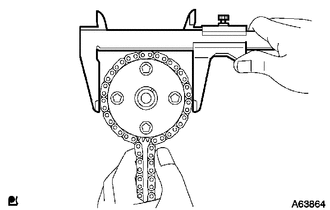
Place the chain sub-assembly around the camshaft timing gear assembly.
Using a vernier caliper, measure the diameter of the camshaft timing gear assembly and chain sub-assembly.
- Minimum Gear Diameter (with Chain):
96.8 mm (3.81 in.)
- NOTICE:
-
The vernier caliper must be in contact with the chain rollers when measuring.
If the diameter is less than the minimum, replace the chain sub-assembly and camshaft timing gear assembly.
13070A
10.INSPECT CAMSHAFT TIMING EXHAUST GEAR ASSEMBLY
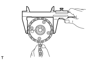
Place the chain sub-assembly around the camshaft timing exhaust gear assembly.
Using a vernier caliper, measure the diameter of the camshaft timing exhaust gear assembly and chain sub-assembly.
- Minimum Gear Diameter (with Chain):
96.8 mm (3.81 in.)
- NOTICE:
-
The vernier caliper must be in contact with the chain rollers when measuring.
If the diameter is less than the minimum, replace the chain sub-assembly and camshaft timing exhaust gear assembly.
13521
11.INSPECT CRANKSHAFT TIMING SPROCKET
Place the chain sub-assembly around the crankshaft timing sprocket.
Using a vernier caliper, measure the diameter of the crankshaft timing sprocket and chain sub-assembly.
- Minimum Gear Diameter (with Chain):
51.1 mm (2.01 in.)
- NOTICE:
-
The vernier caliper must be in contact with the chain rollers when measuring.
If the diameter is less than the minimum, replace the chain sub-assembly and crankshaft timing sprocket.
13559
12.INSPECT CHAIN TENSIONER SLIPPER
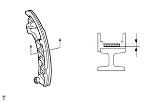
Using a vernier caliper, measure the chain tensioner slipper wear.
- Maximum Wear:
1.0 mm (0.0394 in.)
If the wear is greater than the maximum, replace the chain tensioner slipper.
13561
13.INSPECT NO. 1 CHAIN VIBRATION DAMPER
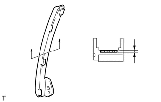
Using a vernier caliper, measure the No. 1 chain vibration damper wear.
- Maximum Wear:
1.0 mm (0.0394 in.)
If the wear is greater than the maximum, replace the No. 1 chain vibration damper.
13562
14.INSPECT NO. 2 CHAIN VIBRATION DAMPER
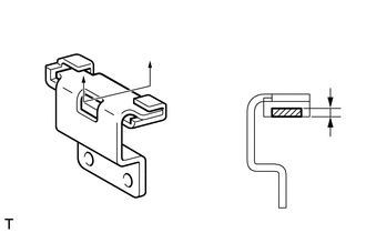
Using a vernier caliper, measure the No. 2 chain vibration damper wear.
- Maximum Wear:
1.0 mm (0.0394 in.)
If the wear is greater than the maximum, replace the No. 2 chain vibration damper.
13549
15.INSPECT CHAIN TENSIONER PLATE
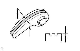
Using a vernier caliper, measure the chain tensioner plate wear.
- Maximum Wear:
1.0 mm (0.0394 in.)
If the wear is greater than the maximum, replace the chain tensioner plate.
13540
16.INSPECT NO. 1 CHAIN TENSIONER ASSEMBLY
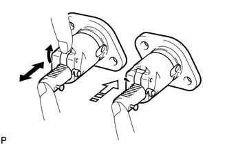
| *a | Raise |
| *b | Move |
| *c | Lock |
Check that the plunger moves smoothly when the ratchet pawl is raised with your finger.
Release the ratchet pawl, then check that the plunger is locked in place by the ratchet pawl and does not move when pushed with your finger.
13511
17.INSPECT CAMSHAFT
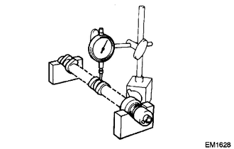
Inspect the camshaft for runout.
Place the camshaft on V-blocks.
Using a dial indicator, measure the runout at the center journal.
- Maximum Runout:
0.04 mm (0.00157 in.)
If the runout is greater than the maximum, replace the camshaft.
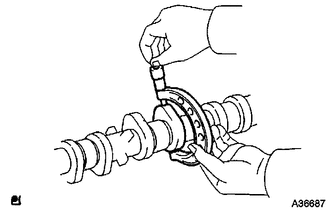
Inspect the cam lobes.
Using a micrometer, measure the cam lobe height.
- Standard Cam Lobe Height:
42.816 to 42.916 mm (1.6857 to 1.6896 in.)
- Minimum Cam Lobe Height:
42.666 mm (1.6798 in.)
If the cam lobe height is less than the minimum, replace the camshaft.
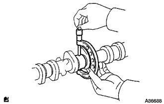
Inspect the camshaft journals.
Using a micrometer, measure the journal diameter.
- Standard Journal Diameter:
Journal Position Specified Condition No. 1 34.449 to 34.465 mm (1.35626 to 1.35689 in.) Other 22.949 to 22.965 mm (0.90350 to 0.90413 in.)
If the journal diameter is not as specified, check the oil clearance.
Click hereEngine / Hybrid System>2ZR-FE ENGINE MECHANICAL>CYLINDER HEAD>INSPECTION
13512
18.INSPECT NO. 2 CAMSHAFT
Inspect the No. 2 camshaft for runout.
Place the No. 2 camshaft on V-blocks.
Using a dial indicator, measure the runout at the center journal.
- Maximum Runout:
0.04 mm (0.00157 in.)
If the runout is greater than the maximum, replace the No. 2 camshaft.
Inspect the cam lobes.
Using a micrometer, measure the cam lobe height.
- Standard Cam Lobe Height:
44.336 to 44.436 mm (1.7455 to 1.7494 in.)
- Minimum Cam Lobe Height:
44.186 mm (1.7396 in.)
If the cam lobe height is less than the minimum, replace the No. 2 camshaft.
Inspect the No. 2 camshaft journals.
Using a micrometer, measure the journal diameter.
- Standard Journal Diameter:
Journal Position Specified Condition No. 1 34.449 to 34.465 mm (1.35626 to 1.35689 in.) Other 22.949 to 22.965 mm (0.90350 to 0.90413 in.)
If the journal diameter is not as specified, check the oil clearance.
Click hereEngine / Hybrid System>2ZR-FE ENGINE MECHANICAL>CYLINDER HEAD>INSPECTION
11101A
19.INSPECT CYLINDER HEAD SET BOLT
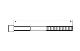
| *a | Measurement Length |
Using a vernier caliper, measure the length of the cylinder head set bolt from the seat to the end.
- Standard Length:
146.8 to 148.2 mm (5.78 to 5.83 in.)
- Maximum Length:
149.2 mm (5.87 in.)
- HINT:
- ·
If the length is greater than the maximum, replace the cylinder head set bolt with a new one. Failure to do so may lead to engine damage.
·If there is any thread deformation, replace the cylinder head set bolt with a new one.
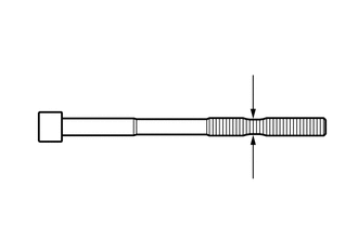
| *a | Measurement Point |
Using a vernier caliper, measure the minimum diameter of the threads at the measurement point.
- Standard Diameter:
9.77 to 9.96 mm (0.385 to 0.392 in.)
- Minimum Diameter:
9.4 mm (0.370 in.)
- HINT:
- ·
If the diameter is less than the minimum, replace the cylinder head set bolt with a new one. Failure to do so may lead to engine damage.
·If there is any thread deformation, replace the cylinder head set bolt with a new one.
17141
20.INSPECT EXHAUST MANIFOLD
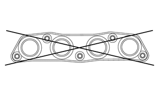
Using a precision straightedge and feeler gauge, measure the warpage on the contact surface of the cylinder head sub-assembly.
- Maximum Warpage:
0.7 mm (0.0276 in.)
If the warpage is greater than the maximum, replace the exhaust manifold.