SUPPLEMENTAL RESTRAINT SYSTEMS SPIRAL CABLE INSTALLATION
PROCEDURE

 84306
1.INSTALL SPIRAL CABLE SUB-ASSEMBLY
84306
1.INSTALL SPIRAL CABLE SUB-ASSEMBLY
Check that the ignition switch is off.
Check that the cable is disconnected from the negative (-) battery terminal.
- CAUTION:
-
Wait at least 90 seconds after disconnecting the cable from the negative (-) battery terminal to disable the SRS system.
Check that the front wheels are facing straight ahead.
Set the turn signal switch to the neutral position.
- NOTICE:
-
If it is not in the neutral position, the turn signal switch pin may break.
Engage the 3 claws to install the spiral cable sub-assembly.
Connect each connector.
45286B
2.INSTALL UPPER STEERING COLUMN COVER
45287
3.INSTALL LOWER STEERING COLUMN COVER
4. ALIGN FRONT WHEELS FACING STRAIGHT AHEAD
5.INSPECT AND ADJUST SPIRAL CABLE
Check that the ignition switch is off.
Check that the cable is disconnected from the negative (-) battery terminal.
- CAUTION:
-
Wait at least 90 seconds after disconnecting the cable from the negative (-) battery terminal to disable the SRS system.
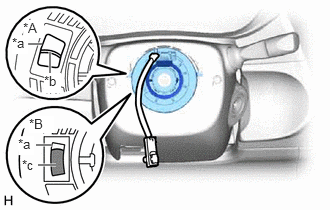
| *A | Flat Cable Type |
| *B | Colored Roller Type |
| *a | Inspection Window |
| *b | Flat Cable |
| *c | Colored Roller |
Check if the spiral cable sub-assembly is centered.
The connector is positioned at the top.
The colored roller or flat cable can be seen in the inspection window.
If the spiral cable sub-assembly is not centered, center it.
- NOTICE:
-
Make sure to observe the following precautions, otherwise the spiral cable sub-assembly may be damaged.
- ·
Do not rotate the spiral cable sub-assembly with the battery connected and the ignition switch ON.
·Release the interlock before rotating the spiral cable sub-assembly.
·Do not rotate the spiral cable sub-assembly using the airbag wire harness.
·Do not rotate the spiral cable sub-assembly with excessive force.
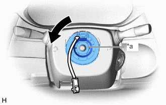
| *a | Interlock |
While pushing on the interlock shown in the illustration, rotate the spiral cable sub-assembly counterclockwise slowly by hand until it stops.
- NOTICE:
-
If the spiral cable sub-assembly is rotated clockwise in this step, it may be damaged and may no longer be able to be centered. Make sure to only rotate the spiral cable sub-assembly counterclockwise.
- HINT:
-
If the interlock is engaged, the spiral cable sub-assembly will lock when the connector is near at the top or bottom of the rotation of the spiral cable sub-assembly.
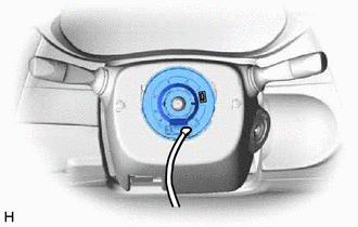
If the connector is not positioned at the bottom of the rotation of the spiral cable sub-assembly when the spiral cable sub-assembly is turned until it stops, turn the spiral cable sub-assembly clockwise until the connector is positioned at the bottom as shown in the illustration.
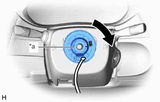
| *a | Interlock |
While pushing on the interlock shown in the illustration, rotate the spiral cable sub-assembly clockwise approximately 2.5 times.
- NOTICE:
-
If the spiral cable sub-assembly is rotated clockwise 5 times or more from the point at which it stops and the connector is positioned at the bottom, the spiral cable sub-assembly may be damaged.
- HINT:
-
If the interlock is engaged, the spiral cable sub-assembly will lock when the connector is near at the top or bottom of the rotation of the spiral cable sub-assembly.
| *A | Flat Cable Type |
| *B | Colored Roller Type |
| *a | Inspection Window |
| *b | Flat Cable |
| *c | Colored Roller |
Check that the spiral cable sub-assembly is centered.
The connector is positioned at the top.
The colored roller or flat cable can be seen in the inspection window.
- NOTICE:
-
If the spiral cable sub-assembly cannot be centered, it may be damaged. Replace the spiral cable sub-assembly with a new one.
45100
6.INSTALL STEERING WHEEL ASSEMBLY