2NZ-FE ENGINE CONTROL HEATED OXYGEN SENSOR INSTALLATION
PROCEDURE

 89465
1.INSTALL HEATED OXYGEN SENSOR
89465
1.INSTALL HEATED OXYGEN SENSOR
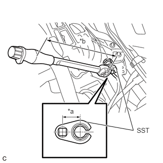
| *a | Length of SST 30 mm (1.18 in.) |
| *b | Length of Torque Wrench 260 mm (10.2 in.) |
Using SST, install the heated oxygen sensor to the exhaust manifold.
- SST
- 09224-00010
- Torque:
- without SST [Torque (N*m (kgf*cm, ft.*lbf))] : 44 N*m (449 kgf*cm, 32 ft.*lbf)
- with SST [Reading of Torque wrench (N*m (kgf*cm, ft.*lbf))] : 39 N*m (398 kgf*cm, 29 ft.*lbf)
- NOTICE:
-
If the heated oxygen sensor has been struck or dropped, replace it.
- HINT:
- ·
This torque value is effective when SST is parallel to the torque wrench.
·The "with SST" torque value is effective when using SST with a fulcrum length of 30 mm (1.18 in.).
·The "with SST" torque value is effective when using a torque wrench with a fulcrum length of 260 mm (10.2 in.).
·If using a torque wrench with a different length, or connecting the torque wrench and SST at an angle, refer to the alternate torque values.
Click hereGeneral>INTRODUCTION>REPAIR INSTRUCTION>PRECAUTION
Engage the 2 wire harness clamps and connect the heated oxygen sensor connector.
2.INSPECT FOR EXHAUST GAS LEAK