2NZ-FE ENGINE CONTROL CAMSHAFT OIL CONTROL VALVE INSPECTION
PROCEDURE

 11101J
1.INSPECT CAMSHAFT TIMING OIL CONTROL VALVE ASSEMBLY
a.
Measure the resistance according to the value(s) in the table below.
- Standard Resistance:
Tester Connection Condition Specified Condition 1 - 2 20°C (68°F) 6.9 to 7.9 Ω
If the result is not as specified, replace the camshaft timing oil control valve assembly.
b.
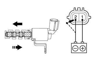
Check the operation.
i.

0.927,1.146 1.073,0.646
1.073,0.646 1.26,0.646
false
0.073,0.094 0.385,0.25
0.313,0.156
10
false
*a
0.563,0.573 0.875,0.729
0.313,0.156
10
false
*b
0.573,1.813 0.885,1.969
0.313,0.156
10
false
*c
1.313,0.542 1.625,0.698
0.313,0.156
10
false
*d
| *a | Component without harness connected
(Camshaft Timing Oil Control Valve Assembly) |
| *b | When Applied |
| *c | When Cut Off |
| *d | Spool Valve |
Connect a battery positive (+) lead to terminal 1 and negative (-) lead to terminal 2, and check the movement of the spool valve.
- OK:
Condition Specified Condition Battery voltage applied Valve moves in left arrow direction shown in illustration Battery voltage cut off Valve moves in right arrow direction shown in illustration
- NOTICE:
-
Accumulation of foreign matter can cause minor pressure leaks. Minor pressure leaks will cause the camshaft to advance or retard, and this will cause a DTC to be stored.
If the result is not as specified, replace the camshaft timing oil control valve assembly.