LIGHTING (INT)  LIGHTING SYSTEM  Interior Light Auto Cut Circuit  


DESCRIPTION

The main body ECU (multiplex network body ECU) controls operation of the DOME CUT relay in order to supply power to the interior lights.

WIRING DIAGRAM
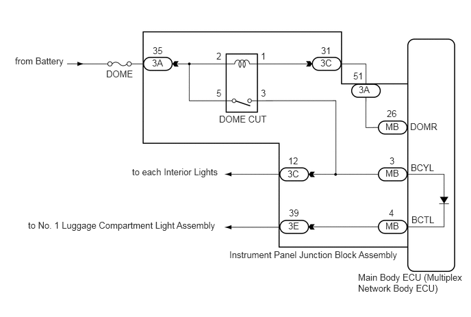
E296292E01
0.229,0.844 1.125,1.094 0.896,0.25 10 false from Battery 1.615,1.042 2.115,1.25 0.5,0.208 10 false DOME 3.333,1.729 4.177,1.948 0.844,0.219 10 false DOME CUT 6.25,2.469 6.677,2.677 0.427,0.208 10 false BCYL 6.26,3.26 6.698,3.479 0.438,0.219 10 false BCTL 2.01,2.531 3.469,2.74 1.458,0.208 10 false to each Interior Lights 0.427,3.344 3.365,3.563 2.938,0.219 10 false to No. 1 Luggage Compartment Light Assembly 3.49,3.792 6.219,4.021 2.729,0.229 10 false Instrument Panel Junction Block Assembly 5.448,4.135 7.135,4.573 1.688,0.438 10 false Main Body ECU (Multiplex Network Body ECU) 2.313,0.875 2.573,1.073 0.26,0.198 10 false 3A 4.875,0.875 5.135,1.073 0.26,0.198 10 false 3C 5.458,1.281 5.74,1.479 0.281,0.198 10 false 3A 5.865,2.552 6.146,2.75 0.281,0.198 10 false MB 4.375,2.563 4.635,2.76 0.26,0.198 10 false 3C 4.385,3.354 4.646,3.552 0.26,0.198 10 false 3E 5.865,3.354 6.146,3.552 0.281,0.198 10 false MB 2.323,0.688 2.583,0.885 0.26,0.198 10 false 35 4.885,0.688 5.146,0.885 0.26,0.198 10 false 31 4.385,2.365 4.646,2.563 0.26,0.198 10 false 12 4.396,3.156 4.656,3.354 0.26,0.198 10 false 39 5.927,2.365 6.188,2.563 0.26,0.198 10 false 3 5.917,3.156 6.177,3.354 0.26,0.198 10 false 4 5.865,1.844 6.146,2.042 0.281,0.198 10 false MB 5.375,1.073 5.635,1.271 0.26,0.198 10 false 51 5.885,1.646 6.146,1.844 0.26,0.198 10 false 26 6.24,1.844 6.74,2.052 0.5,0.208 10 false DOMR 3.969,0.771 4.229,0.969 0.26,0.198 10 false 1 3.292,0.771 3.552,0.969 0.26,0.198 10 false 2 3.969,1.333 4.229,1.531 0.26,0.198 10 false 3 3.292,1.333 3.552,1.531 0.26,0.198 10 false 5

CAUTION / NOTICE / HINT

NOTICE:

Inspect the fuses for circuits related to this system before performing the following procedure.


PROCEDURE

1.PERFORM ACTIVE TEST USING GTS
a.

Connect the GTS to the DLC3.


b.

Turn the ignition switch to ON.


c.

Turn the GTS on.


d.

Enter the following menus: Body Electrical / Main Body / Active Test.


e.

Perform the Active Test according to the display on the GTS.

Body Electrical > Main Body > Active Test
Tester Display Measurement Item Control Range Diagnostic Note
Relay for Interior Light Auto Cut Function DOME CUT relay ON or OFF When performing this Active Test, turn on all the interior lights.
·

ON: DOME CUT relay off (interior lights turn off)

·

OFF: DOME CUT relay on (interior lights turn on)


Body Electrical > Main Body > Active Test
Tester Display
Relay for Interior Light Auto Cut Function
50004 123 66
OK:

DOME CUT relay operates.


Result:
Proceed to
OK
NG


OK

PROCEED TO NEXT SUSPECTED AREA SHOWN IN PROBLEM SYMPTOMS TABLE

NG

2.CHECK HARNESS AND CONNECTOR (BATTERY - INSTRUMENT PANEL JUNCTION BLOCK ASSEMBLY)
a.

Measure the voltage according to the value(s) in the table below.
Standard Voltage:
Tester Connection Condition Specified Condition
3A-51 - Body ground Always 11 to 14 V


Result:
Proceed to
OK
NG


OK

3.INSPECT INSTRUMENT PANEL JUNCTION BLOCK ASSEMBLY

NG

5.CHECK HARNESS AND CONNECTOR (BATTERY - INSTRUMENT PANEL JUNCTION BLOCK ASSEMBLY)
3.INSPECT INSTRUMENT PANEL JUNCTION BLOCK ASSEMBLY
a.

Remove the instrument panel junction block assembly.

Click herePower Source / Network>POWER DISTRIBUTION>MAIN BODY ECU>REMOVAL


b.

Remove the main body ECU (multiplex network body ECU) from instrument panel junction block assembly.

Click herePower Source / Network>POWER DISTRIBUTION>MAIN BODY ECU>REMOVAL


c.

Measure the voltage according to the value(s) in the table below.
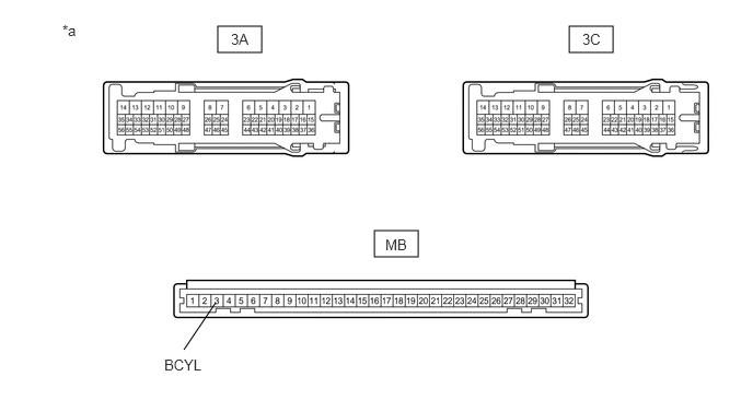
E296399C01
2.073,0.25 2.49,0.5 0.417,0.25 5.417,0.25 5.833,0.5 0.417,0.25 3.563,2.198 3.979,2.448 0.417,0.25 1.75,3.333 2.052,2.885 false 0.594,0.208 0.906,0.365 0.313,0.156 10 false *a 2.198,0.292 2.583,0.542 0.385,0.25 10 false 3A 5.542,0.292 5.927,0.542 0.385,0.25 10 false 3C 3.667,2.25 4.052,2.5 0.385,0.25 10 false MB 1.563,3.396 2.156,3.583 0.594,0.188 10 false BCYL
*a Component without harness connected
(Instrument Panel Junction Block Assembly)
- -


Standard Voltage:
Tester Connection Condition Specified Condition
3C-12 - Battery negative terminal Battery positive (+) → 3A-35
Battery negative (-) → 3C-31
11 to 14 V
MB-3(BCYL) - Battery negative terminal Battery positive (+) → 3A-35
Battery negative (-) → 3C-31
11 to 14 V


Result:
Proceed to
OK
NG


OK

4.INSPECT INSTRUMENT PANEL JUNCTION BLOCK ASSEMBLY

NG

REPLACE INSTRUMENT PANEL JUNCTION BLOCK ASSEMBLY

4.INSPECT INSTRUMENT PANEL JUNCTION BLOCK ASSEMBLY
a.

Measure the resistance according to the value(s) in the table below.
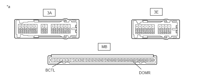
E283690C09
1.563,0.333 2,0.594 0.438,0.26 5.438,0.302 5.875,0.563 0.438,0.26 3.552,1.573 3.99,1.833 0.438,0.26 5.115,2.521 4.802,2.229 false 1.885,2.438 2.26,2.229 false 1.708,0.385 2.031,0.646 0.323,0.26 10 false 3A 5.573,0.354 5.896,0.615 0.323,0.26 10 false 3E 3.677,1.615 4,1.875 0.323,0.26 10 false MB 5.031,2.563 5.823,2.74 0.792,0.177 10 false DOMR 1.646,2.469 2.052,2.729 0.406,0.26 10 false BCTL 0.24,0.156 0.552,0.354 0.313,0.198 10 false *a
*a Component without harness connected
(Instrument Panel Junction Block Assembly)
- -


Standard Resistance:
Tester Connection Condition Specified Condition
3A-51 - MB-26 (DOMR) Always Below 1 Ω
3E-39 - MB-4 (BCTL) Always Below 1 Ω


Result:
Proceed to
OK
NG


OK

REPLACE MAIN BODY ECU (MULTIPLEX NETWORK BODY ECU)

NG

REPLACE INSTRUMENT PANEL JUNCTION BLOCK ASSEMBLY

5.CHECK HARNESS AND CONNECTOR (BATTERY - INSTRUMENT PANEL JUNCTION BLOCK ASSEMBLY)
a.

Disconnect the 3A instrument panel junction block assembly connectors.


b.

Measure the voltage according to the value(s) in the table below.

Standard Voltage:
Tester Connection Condition Specified Condition
3A-35 - Body ground Always 11 to 14 V


Result:
Proceed to
OK
NG


OK

6.CHECK HARNESS AND CONNECTOR (INSTRUMENT PANEL JUNCTION BLOCK ASSEMBLY - INSTRUMENT PANEL JUNCTION BLOCK ASSEMBLY)

NG

REPAIR OR REPLACE HARNESS OR CONNECTOR

6.CHECK HARNESS AND CONNECTOR (INSTRUMENT PANEL JUNCTION BLOCK ASSEMBLY - INSTRUMENT PANEL JUNCTION BLOCK ASSEMBLY)
a.

Disconnect the 3C instrument panel junction block assembly connectors.


b.

Measure the resistance according to the value(s) in the table below.

Standard Resistance:
Tester Connection Condition Specified Condition
3C-31 - 3A-51 Always Below 1 Ω
3C-31 or 3A-51 - Body ground Always 10 kΩ or higher


Result:
Proceed to
OK
NG


OK

7.INSPECT INSTRUMENT PANEL JUNCTION BLOCK ASSEMBLY

NG

REPAIR OR REPLACE HARNESS OR CONNECTOR

7.INSPECT INSTRUMENT PANEL JUNCTION BLOCK ASSEMBLY
a.

Remove the instrument panel junction block assembly.

Click herePower Source / Network>POWER DISTRIBUTION>MAIN BODY ECU>REMOVAL


b.

Measure the resistance according to the value(s) in the table below.

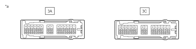
E283437C01
5.125,0.281 5.458,0.542 0.333,0.26 1.656,0.271 1.99,0.531 0.333,0.26 0.188,0.146 0.5,0.344 0.313,0.198 10 false *a 1.74,0.323 2.052,0.521 0.313,0.198 10 false 3A 5.198,0.323 5.51,0.521 0.313,0.198 10 false 3C
*a Component without harness connected
(Instrument Panel Junction Block Assembly)
- -


Standard Resistance:
Tester Connection Condition Specified Condition
3A-35 - 3C-31 Always Below 1 Ω


Result:
Proceed to
OK
NG


OK

REPLACE MAIN BODY ECU (MULTIPLEX NETWORK BODY ECU)

NG

REPLACE INSTRUMENT PANEL JUNCTION BLOCK ASSEMBLY