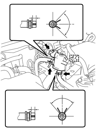
2NZ-FE EMISSION CONTROL PURGE VALVE INSTALLATION
PROCEDURE

 25860
1.INSTALL PURGE VALVE (PURGE VSV)
a.
Install the purge valve (purge VSV) to the air cleaner cap sub-assembly.
b.

1.25,2.823 1.479,2.823
1.479,2.823 1.594,2.208
true
2.229,2.823 2.646,2.823
true
2.198,1.927 2.198,1.573
2.198,1.573 2.333,1.573
true
1.042,2.76 1.313,2.969
0.271,0.208
10
false
*1
2.698,2.74 2.938,2.99
0.24,0.25
10
true
*2
1.135,0.323 1.458,0.531
0.323,0.208
10
false
*a
2.5,0.635 2.813,0.792
0.313,0.156
10
false
*b
1.802,0.219 2.115,0.438
0.313,0.219
10
false
*c
2.698,4.052 3,4.281
0.302,0.229
10
false
*d
2.146,3.24 2.406,3.427
0.26,0.188
10
true
*e
2.708,0.771 2.927,0.979
0.219,0.208
10
true
*e
1.094,3.594 1.417,3.802
0.323,0.208
10
false
*a
1.969,3.323 2.24,3.542
0.271,0.219
10
false
*b
2.354,1.49 2.594,1.74
0.24,0.25
10
true
*3
| *1 | No. 1 Fuel Vapor Feed Hose |
| *2 | No. 2 Fuel Vapor Feed Hose |
| *3 | Purge Valve (Purge VSV) |
| *a | 1 to 5 mm (0.0394 to 0.197 in.) |
| *b | 90° |
| *c | Upper |
| *d | Front |
| *e | RH |
Connect the No. 1 fuel vapor feed hose and No. 2 fuel vapor feed hose to the purge valve (purge VSV) and slide the 2 clips to secure them.
- HINT:
-
Engage the clip within the area shown in the illustration.
c.
Engage the wire harness clamp to the purge valve (purge VSV).
d.
Connect the purge valve (purge VSV) connector.