2ZR-FE EMISSION CONTROL PURGE VALVE INSTALLATION
PROCEDURE

 17650G
1.INSTALL PURGE VALVE (PURGE VSV)
a.
Install the purge valve (purge VSV) to the air tube with the screw.
- Torque:
- 3.4 N*m (35 kgf*cm, 30 in.*lbf)
b.

0.375,1.771 0.854,1.771
true
1.781,1.74 2.698,1.74
true
2.771,1.677 3.01,1.865
0.24,0.188
10
true
*1
0.135,1.688 0.448,1.844
0.313,0.156
10
false
*2
1.281,2.833 1.594,2.99
0.313,0.156
10
false
*a
1.938,2.896 2.25,3.052
0.313,0.156
10
false
*b
2.51,2.563 2.823,2.719
0.313,0.156
10
false
*c
1.573,3.417 1.885,3.573
0.313,0.156
10
false
*d
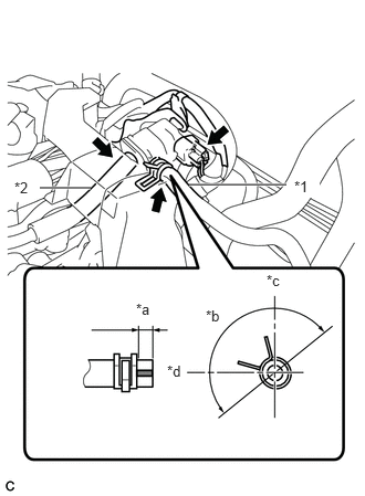
| *1 | No. 1 Fuel Vapor Feed Hose |
| *2 | No. 2 Fuel Vapor Feed Hose |
| *a | 1 to 5 mm (0.0394 to 0.197 in.) |
| *b | 180° |
| *c | Upper |
| *d | Front |
Connect the No. 2 fuel vapor feed hose to the purge valve (purge VSV).
c.
Connect the No. 1 fuel vapor feed hose to the purge valve (purge VSV) and slide the clip to secure it.
- HINT:
-
Engage the clip within the area shown in the illustration.
d.
Connect the purge valve (purge VSV) connector.

 11212
2.INSTALL NO. 2 CYLINDER HEAD COVER