CLUTCH CLUTCH UNIT(for C50) INSPECTION
PROCEDURE

 31250
1.INSPECT CLUTCH DISC ASSEMBLY
31250
1.INSPECT CLUTCH DISC ASSEMBLY
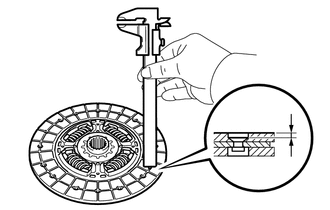
Using a vernier caliper, measure the rivet head depth.
- Minimum Rivet Head Depth:
0.3 mm (0.0118 in.)
If the rivet head depth is less than the minimum, replace the clutch disc assembly.
Install the clutch disc assembly to the manual transaxle assembly.
- HINT:
-
Insert the clutch disc assembly in the correct direction.
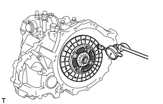
Using a dial gauge, measure the clutch disc assembly runout.
- Maximum Runout:
0.8 mm (0.0315 in.)
If the runout is more than the maximum, replace the clutch disc assembly.
31210
2.INSPECT CLUTCH COVER ASSEMBLY
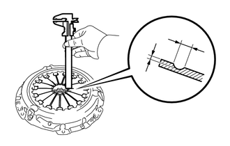
Using a vernier caliper, measure the depth and width of the diaphragm spring wear.
- Maximum:
Depth (A): 0.5 mm (0.0197 in.)
Width (B): 6.0 mm (0.236 in.)
If the depth or width is more than the maximum, replace the clutch cover assembly.
13405
3.INSPECT FLYWHEEL SUB-ASSEMBLY
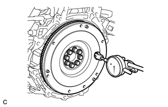
Using a dial gauge, check the flywheel sub-assembly runout.
- Maximum Runout:
0.1 mm (0.00394 in.)
If the runout is more than the maximum, replace the flywheel sub-assembly.
31230
4.INSPECT CLUTCH RELEASE BEARING ASSEMBLY
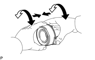
Check that the clutch release bearing assembly moves smoothly without abnormal resistance by turning the sliding parts of the clutch release bearing assembly (clutch cover assembly contacting surface) while applying force in the axial direction.
Inspect the clutch release bearing assembly for damage and wear.
If necessary, replace the clutch release bearing assembly.