DRIVE SHAFT / PROPELLER SHAFT FRONT DRIVE SHAFT ASSEMBLY(for 2NZ-FE) DISASSEMBLY
PROCEDURE

 43448G
1.SEPARATE FRONT NO. 2 AXLE INBOARD JOINT BOOT CLAMP
43448G
1.SEPARATE FRONT NO. 2 AXLE INBOARD JOINT BOOT CLAMP
Hold the drive shaft in a vise between aluminum plates.
- NOTICE:
-
Do not overtighten the vise.
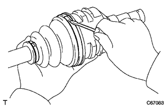
for One Touch Type:
Using a screwdriver, separate the front No. 2 axle inboard joint boot clamp as shown in the illustration.
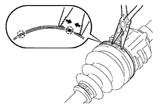
| *a | Claw |
for Claw Engagement Type:
Using needle-nose pliers, disengage the 2 claws as shown in the illustration and separate the front No. 2 axle inboard joint boot clamp.
43448F
2.SEPARATE FRONT AXLE INBOARD JOINT BOOT CLAMP
- HINT:
-
Perform the same procedure as for the front No. 2 axle inboard joint boot clamp.
3.SEPARATE FRONT AXLE INBOARD JOINT BOOT
Separate the front axle inboard joint boot from the front drive inboard joint assembly.
4.REMOVE FRONT DRIVE INBOARD JOINT ASSEMBLY
Remove the old grease from the front drive inboard joint assembly.
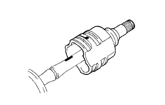
| *a | Matchmark |
Put matchmarks on the front drive inboard joint assembly and front drive outboard joint shaft assembly.
- NOTICE:
-
Do not use a punch for the marks.
Remove the front drive inboard joint assembly from the front drive outboard joint shaft assembly.
Hold the drive shaft in a vise between aluminum plates.
- NOTICE:
-
Do not overtighten the vise.
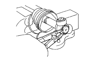
Using a snap ring expander, remove the shaft snap ring from the front drive outboard joint shaft assembly.
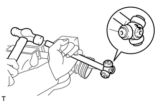
| *a | Matchmark |
Put matchmarks on the front drive outboard joint shaft assembly and tripod joint.
- NOTICE:
-
Do not use a punch for the marks.
Using a brass bar and a hammer, tap out the tripod joint from the front drive outboard joint shaft assembly.
- NOTICE:
- ·
Do not tap the rollers.
·Do not drop the tripod joint.
5.REMOVE FRONT AXLE INBOARD JOINT BOOT
Remove the front No. 2 axle inboard joint boot clamp, front axle inboard joint boot and front axle inboard joint boot clamp.
43474E
6.REMOVE FRONT DRIVE SHAFT DAMPER (for RH Side)
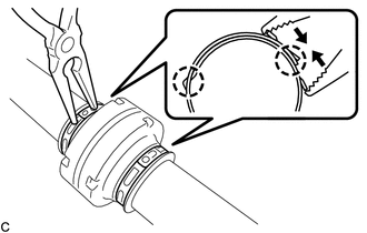
Using needle-nose pliers, disengage the 2 claws as shown in the illustration and separate the 2 front drive shaft damper clamps.
Remove the front drive shaft damper and 2 front drive shaft damper clamps from the front drive outboard joint shaft assembly.
43447F
7.SEPARATE FRONT NO. 2 AXLE OUTBOARD JOINT BOOT CLAMP
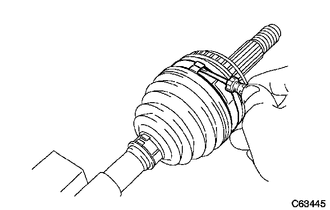
Using a screwdriver, separate the front No. 2 axle outboard joint boot clamp.
43447E
8.SEPARATE FRONT AXLE OUTBOARD JOINT BOOT CLAMP
- HINT:
-
Perform the same procedure as for the front No. 2 axle outboard joint boot clamp.
9.REMOVE FRONT AXLE OUTBOARD JOINT BOOT
Remove the front axle outboard joint boot clamp, front axle outboard joint boot and front No. 2 axle outboard joint boot clamp from the front drive outboard joint shaft assembly.
Remove the old grease from the outboard joint.
41336E
10.REMOVE FRONT DRIVE SHAFT DUST COVER
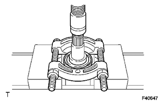
Using SST and a press, remove the front drive shaft dust cover.
- SST
- 09950-00020
- NOTICE:
- ·
Be careful not to drop the front drive inboard joint assembly.
·Do not overtighten SST.